AS-9000 Series Alarm Control Panel Wiring Instructions
1 Installation and Wiring Diagram of the Motherboard
1.1 Power Supply Connection
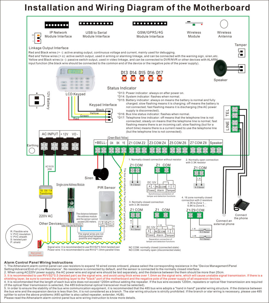
1.1.1 Transformer connection: Two red wires connect to AC 220V input port, while two yellow wires connect to AC input port of main board (had connected by the factory.)
1.1.2 DC12V battery connection: Red wire on the circuit main board connects to the positive pole of acid-lead battery while black wire connects to the negative pole of acid-lead battery.
1.1.3 Auxiliary power output: In case of connecting to external power, if the auxiliary power is short circuit, the alarm control panel will power down no more than 20 seconds and recover. But the auxiliary power output will close. When only AC power supply, if the auxiliary power is overload (not full short), it may cause main board intermittent power supply (similar like jitter).
In case of using battery power supply, should cut the power off immediately, then plug the battery again or use AC power supply.
The auxiliary power current exceed 1.1A for long time (>30 seconds), the auxiliary power output will close and recover automatically after exclude the fault.
1.2 Connection of Wired Sensor (wired zones: zone 1 to zone 16)
1.2.1 Connect signal wire of wired sensors:
| EOL | NO | NC | Zones | |
| 1 | None | √ | 8 | |
| 2 | 3.3K | √ | √ | 8 |
| 3 | 6.8K | √ | √ | 8 |
| 4 | 3.3K+6.8K (expansion) | √ | 16 | |
| 5 | 3.3K+3.3K (tamper) | Tamper | Tamper | 8 |
| 6 | Open circuit | √ | 8 |
1.2.2 Wired sensor power connection: Connect the positive and negative poles of the wired sensor to the 12V output port of the main board (not more than 1A) , and do not connect the positive and negative poles incorrectly. If the current of the connected sensors is more than 1A, please do not use the main board 12V power supply, please use another power supply (such as switching power supply) to power the sensors.
1.2.3 The zones we don’t use can be closed by keypad or shorted.
1.2.4 Enter “Device/Panel setting/More Setting/WTRES” to choose corresponding resistor.
1.2.5 The distance between the alarm control panel and the sensors should be less than 150 meters.
1.3 Connection of Wireless sensor (wireless zones: zone 30 to zone 59)
Please check “set wireless zones” in the quick instruction.
If only use the wireless sensors, should close the wired zones by the below methods: prohibit the wired zones alarm in the system “Device/Panel setting/Wired zones/Enable”.
1.4 Connection of bus zones (bus zones: zone 100 to zone 1999)
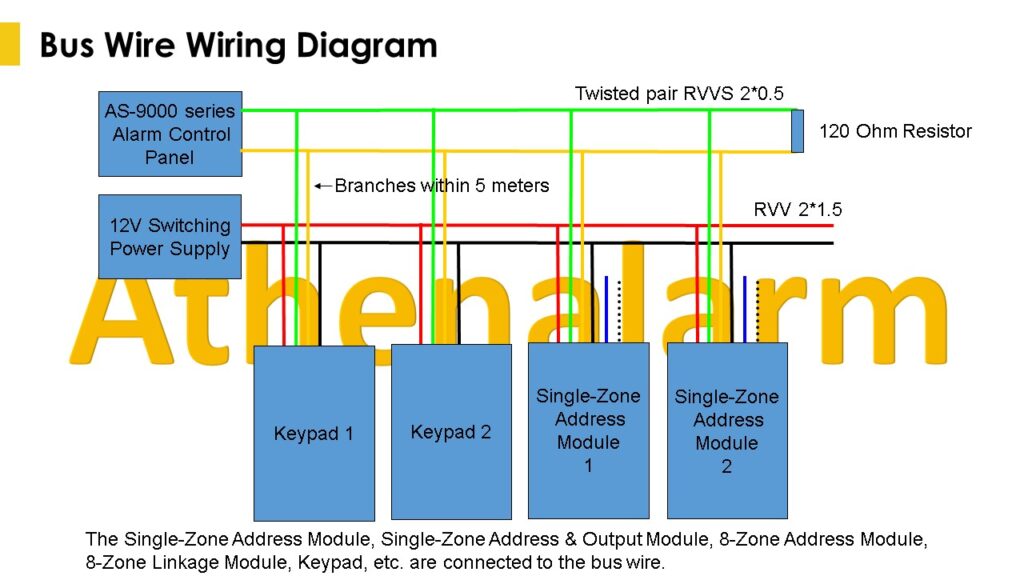
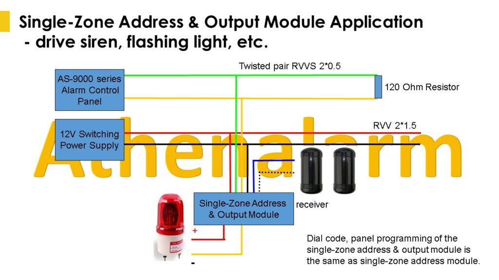
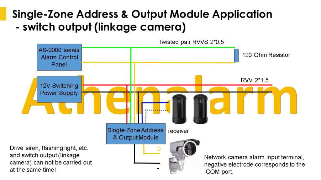
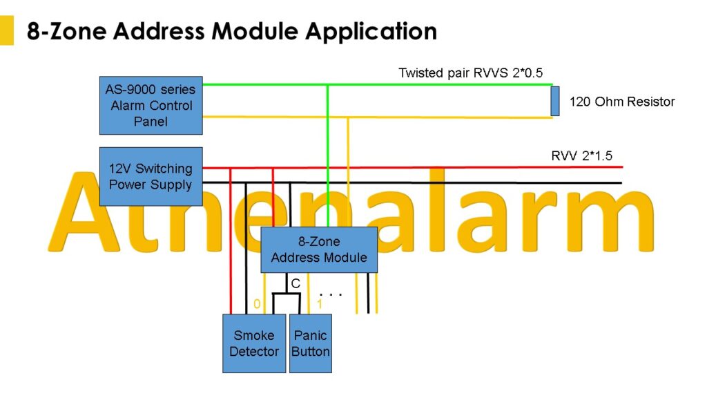
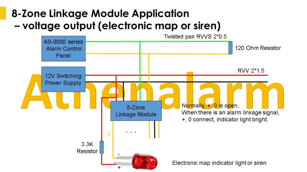
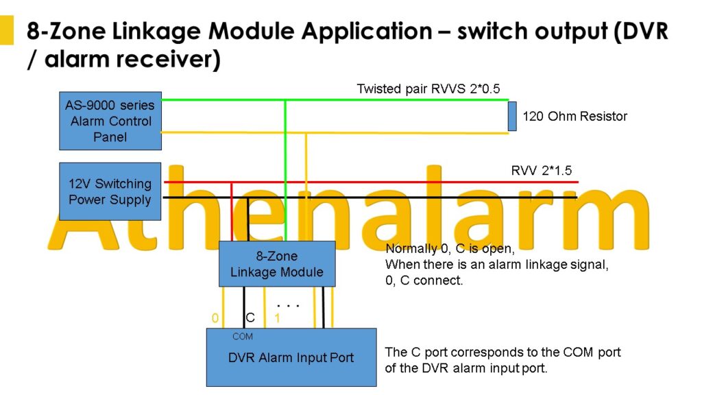
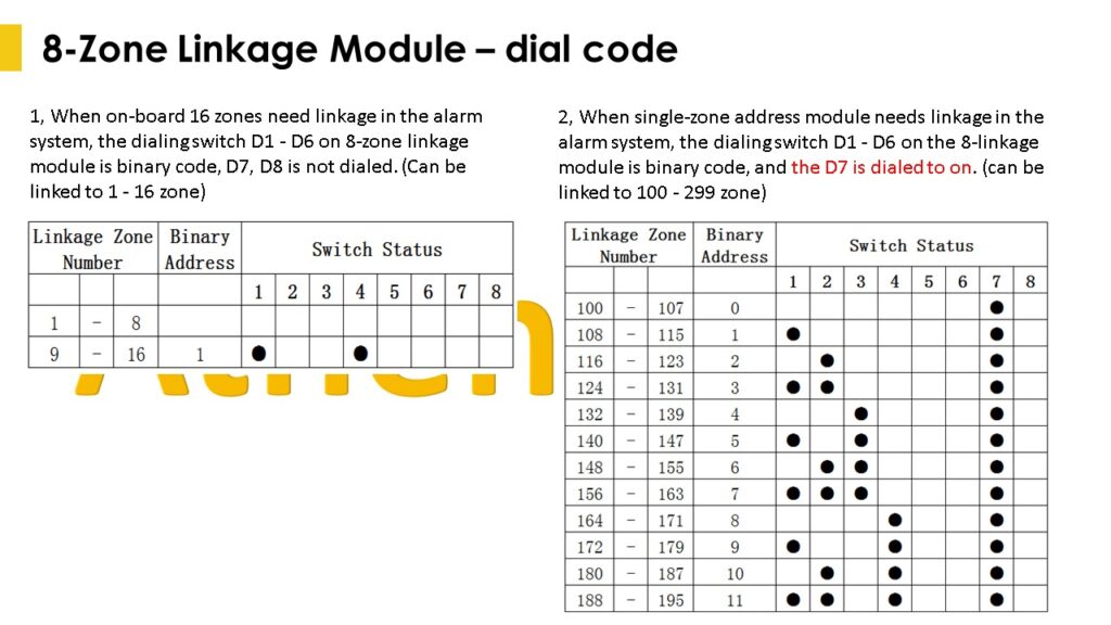
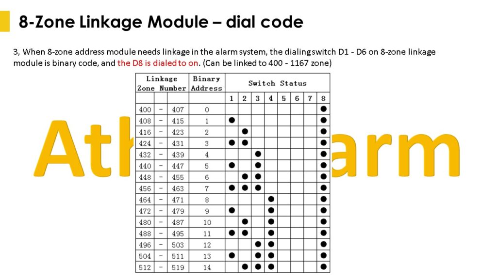
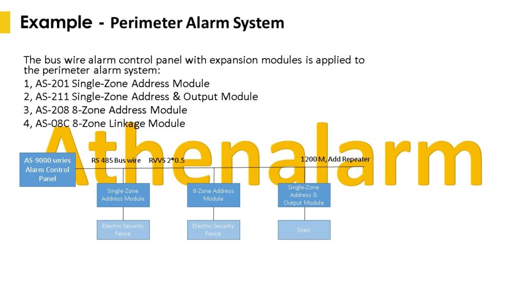
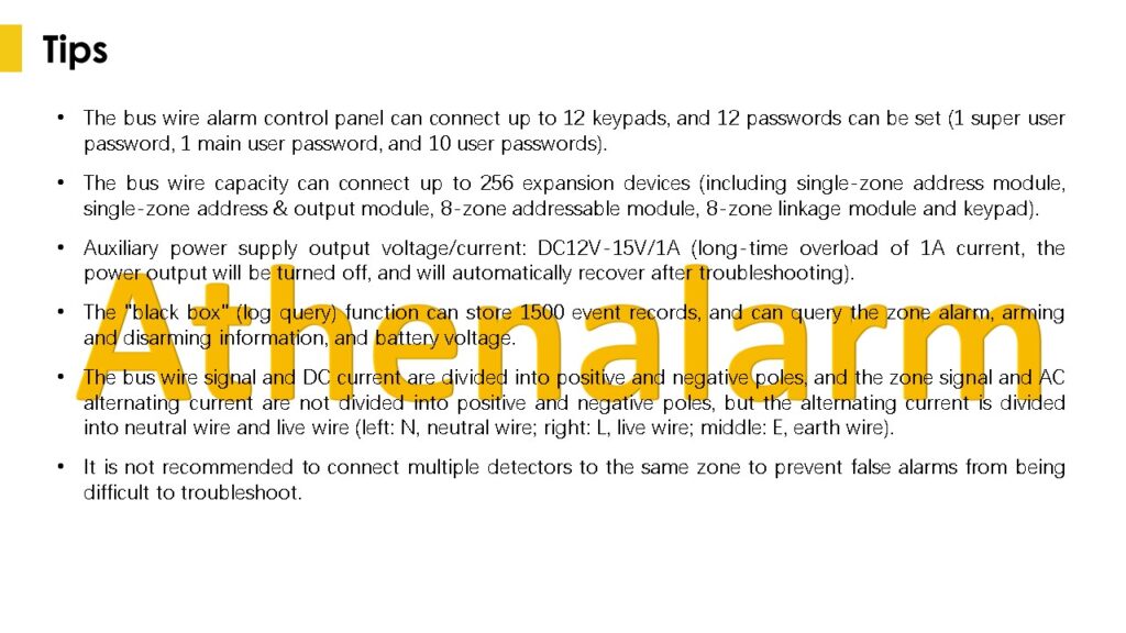
1.4.1 The bus wire can connect up to 256 expansion devices, including single-zone address module, single-zone address module with output, 8-zone address module, 8-zone linkage module and keypad.
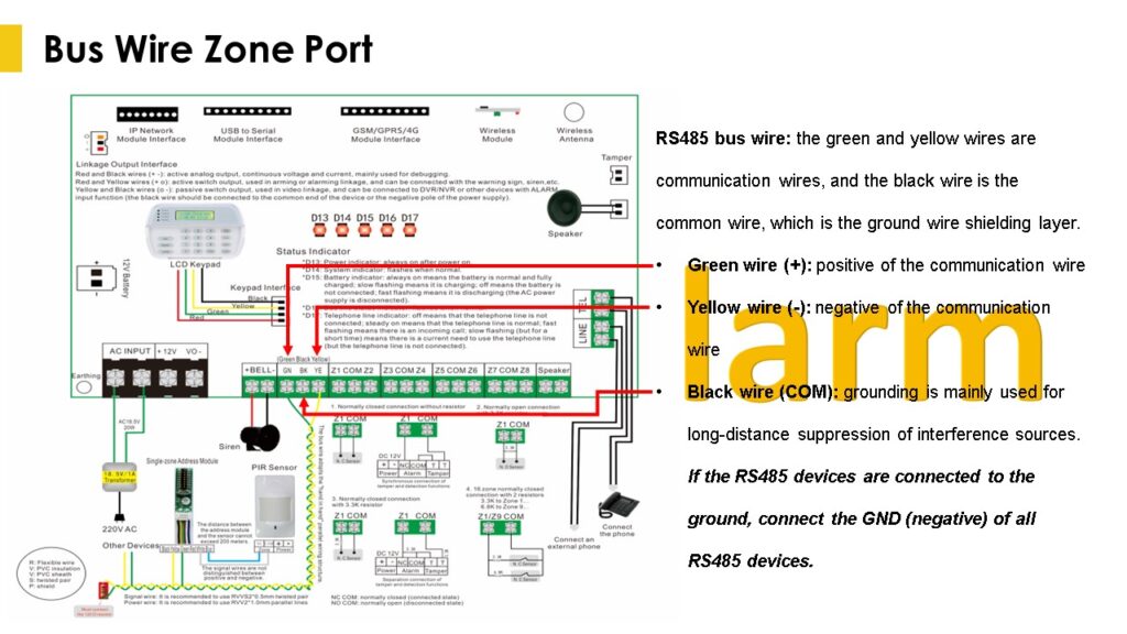
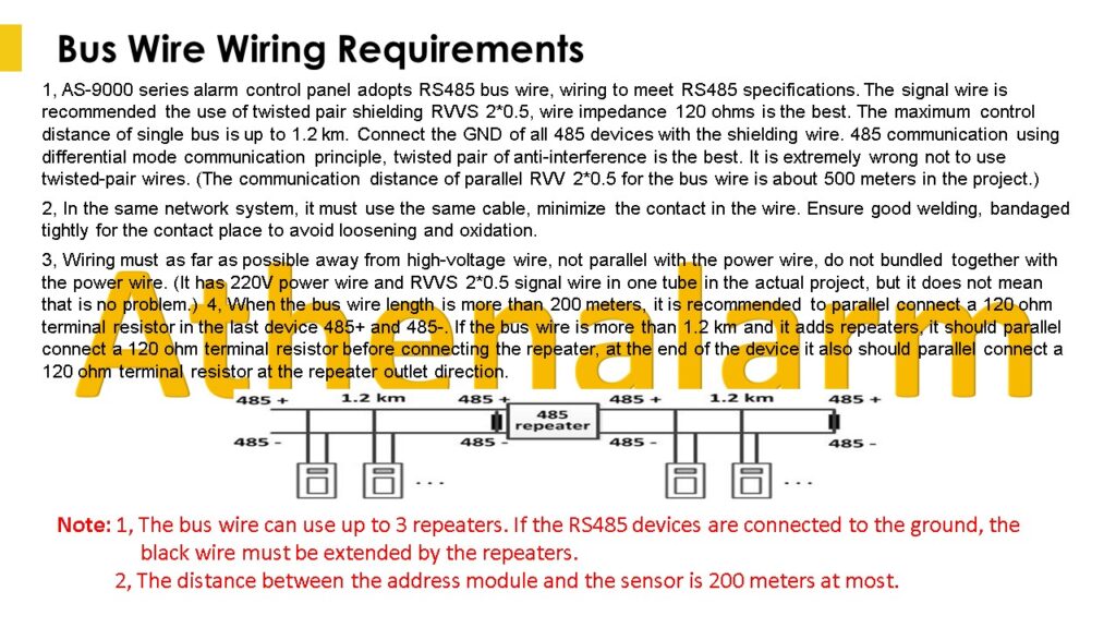
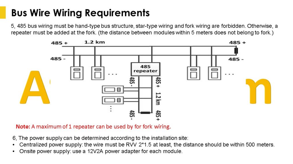
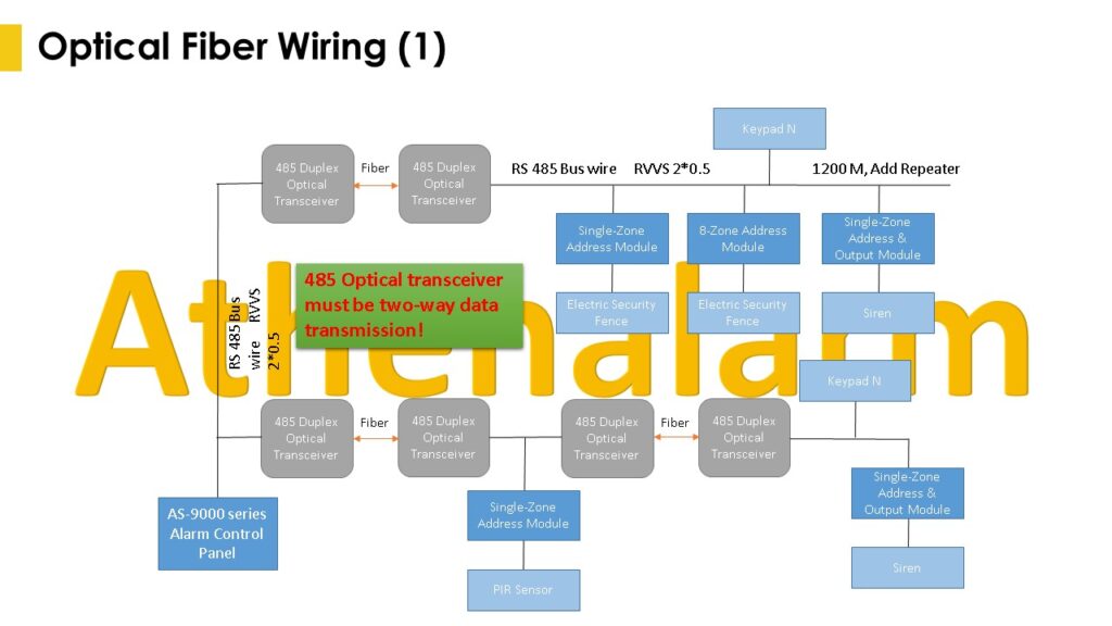
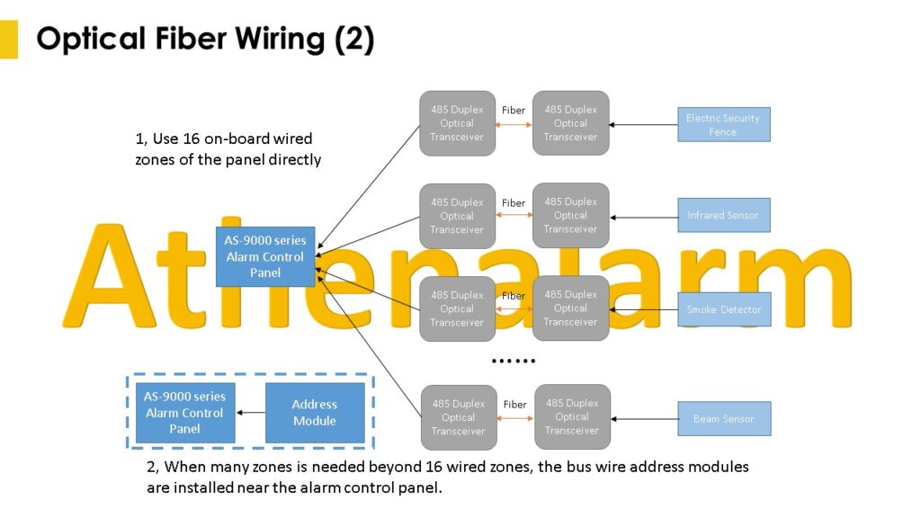
1.4.2 The bus wire wiring requirements: twisted pair shielding RVVS 2*0.5 is recommended, parallel RVV 2*0.5 is not recommended. If the wire has shielding layer, shielding layer must connect to the “black” on the motherboard of the alarm control panel and negative pole of the power of all the expansion modules. When the bus wire length is up to 1200 meters theoretically, a repeater should be added. If optical transceivers are used, the 485 bidirectional optical transceiver must be selected; all bus expansion modules adopt the “hand-in-hand” wiring structure. If there are branches, please use branch device.
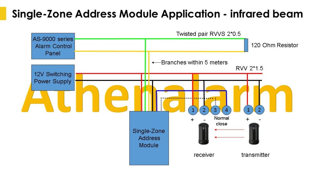
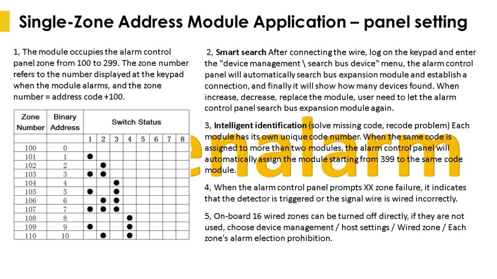
1.4.3 Single-zone address module installation: dialing code base on binary mode, for example, the first zone correspond the bus zone number 101, which is based on the dialing address plus 100 for the bus zone number. If there is a recode or missing code, the alarm control panel automatically will automatically assign the module starting from 399 to the same code module. The number behind the zone code is the bar code number attached to the single-zone address module (please check single-zone address module user manual to learn more).
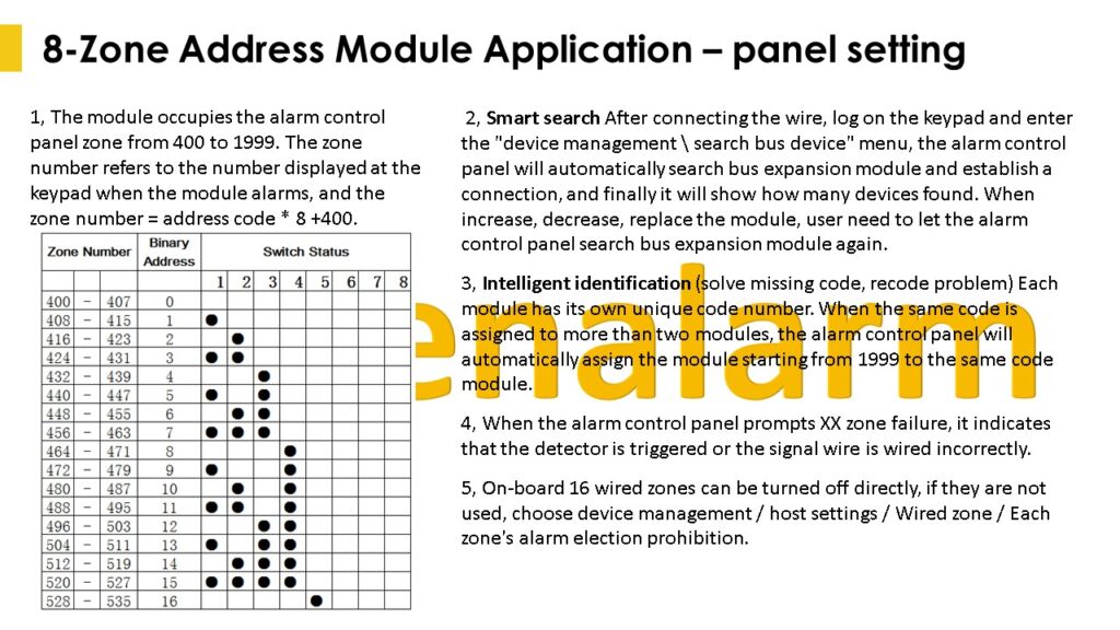
1.4.4 8-zone address module installation: the module occupies the alarm control panel zone from 400 to 1999. The zone number refers to the number displayed at the keypad when the module alarms, and the zone number = address code * 8 +400 (please check 8-zone address module user manual to learn more).
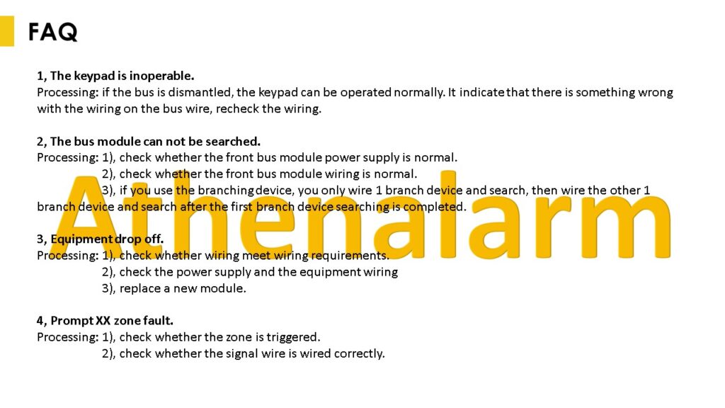
1.4.5 After the wire is connected and powered on, all the bus devices will be found and listed in the “device\Bus scanner”; each time the bus device is added or subtracted, the bus device must be searched again; for example, 10 expansion modules are connected, the number of the bus device will display 10 in the system after searching, that it is correct. If you want to set the bus zone quickly, you can view in the “Common\System Status\Zone’s Status” (8, 9 is a quick page up and down), select the zone need setting and set the type of zone.
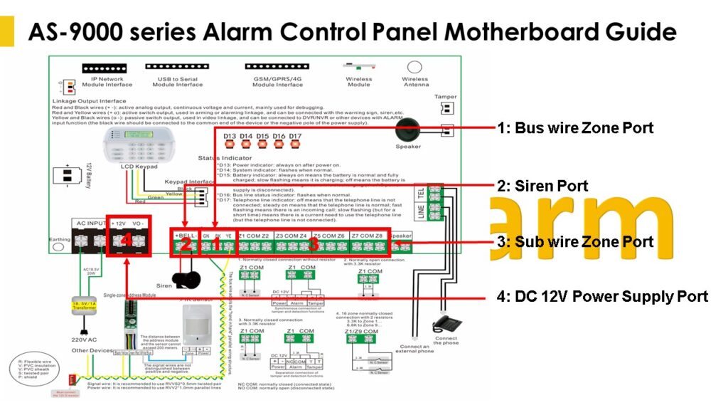
Note: Please read the Athenalarm alarm control panel bus wire wiring instruction to know more details.
1.5 Connection of Siren
Siren port: Connect the positive pole and negative pole of siren to the main board of the alarm control panel bell port.
1.6 Telephone Line Connection
The external telephone line connects to the LINE terminal of main board. The telephone connects to the TEL terminal of main board.
1.7 Installation of Keypad
1.7.1 Keypad connections:
1) Plug the data cable to J3 connector on the back of keypad. Insert another end to J11 white socket of main board.
2) Connect the red and black wires to 12V output port of main board. Pay attention to positive and negative. The green and yellow wires of keypad connect to the corresponding color terminals of main board.
1.7.2 Fix the bracket of keypad and buckle the keypad to it.
1.8 Linkage output interface
Red and black wires(+ -): Active analog output, continuous voltage and current, mainly used for debugging.
Red and yellow wires (+ O): Active switch output, used in arming or alarming linkage, and can be connected with the warning sign, siren, etc.
Black and black wires (O -): Passive switch output, used in video linkage, and be connected to DVR/NVR or other devices with ALARM input function (the black wire should be connected to the common end of the device or the negative pole of the power supply).
1.9 Zone Allocation Table
| Zone No. | Function |
| 1-8 (8 zones) | 8 zones in no resistor or single resistor mode |
| 9-16 (8 zones) | 8 expansion zones in double resistors mode |
| 17 (1 zone) | zone for tamper of the alarm control panel shell |
| 20-27 (8 zones) | zones for wireless remote controls |
| 30-59 (30 zones) | zones for wireless sensors |
| 100-399 (300 zones) | zones for single-zone address modules |
| 400-1999 (1600 zones) | zones for 8-zone address modules |
Warning: Please check and confirm the correct wiring carefully before powering on. Take care to prevent the power wire, the siren wire, the positive and negative pole of the sensor power wire from being reversed, short circuited, or the sensor power wire and signal wires from being short-circuited.
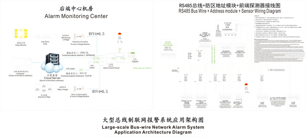
2 Bus-wire Wiring Instruction
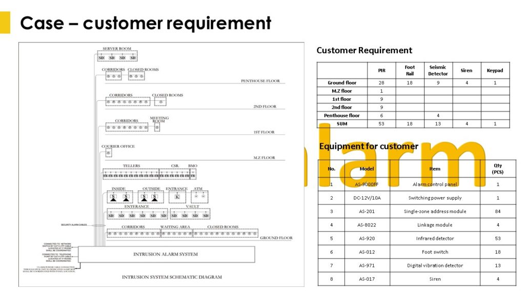
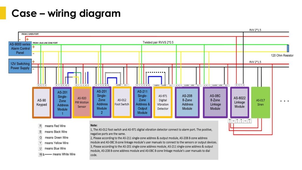
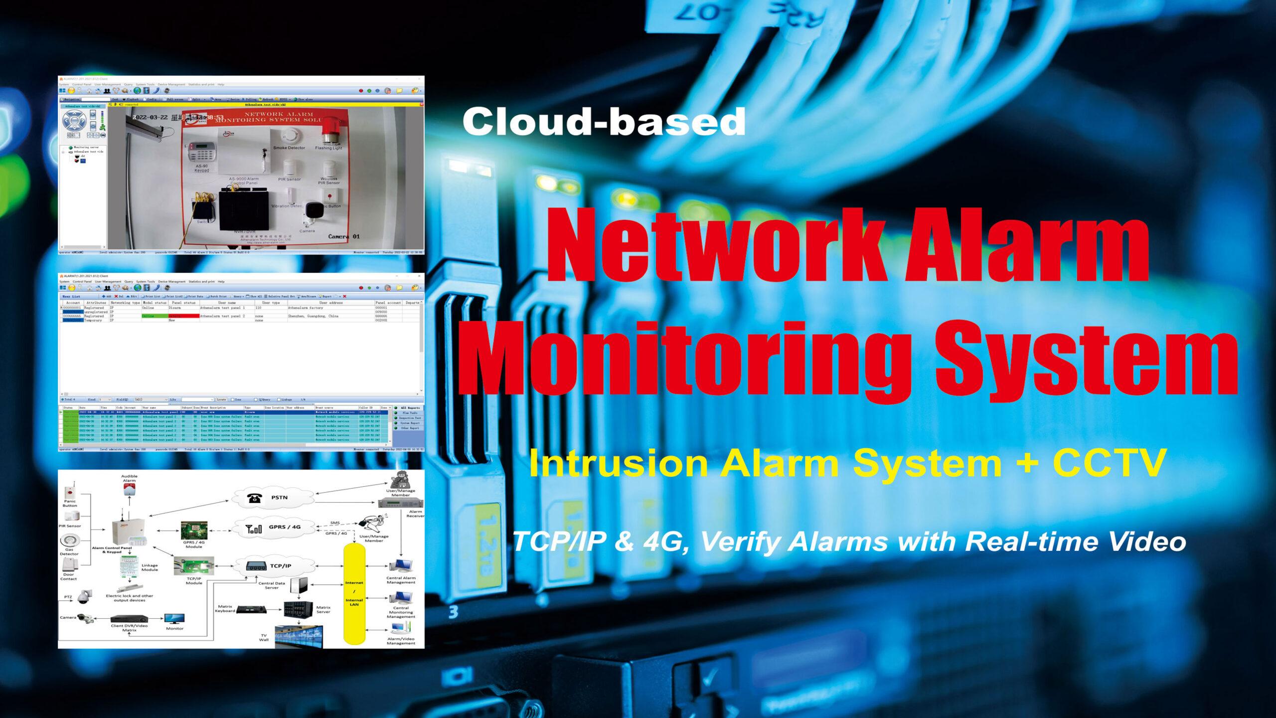
3 Large-scale Bus-wire Network Alarm System Application Architecture Diagram
If you want to obtain high-definition files or have any questions, please feel free to contact us.
