
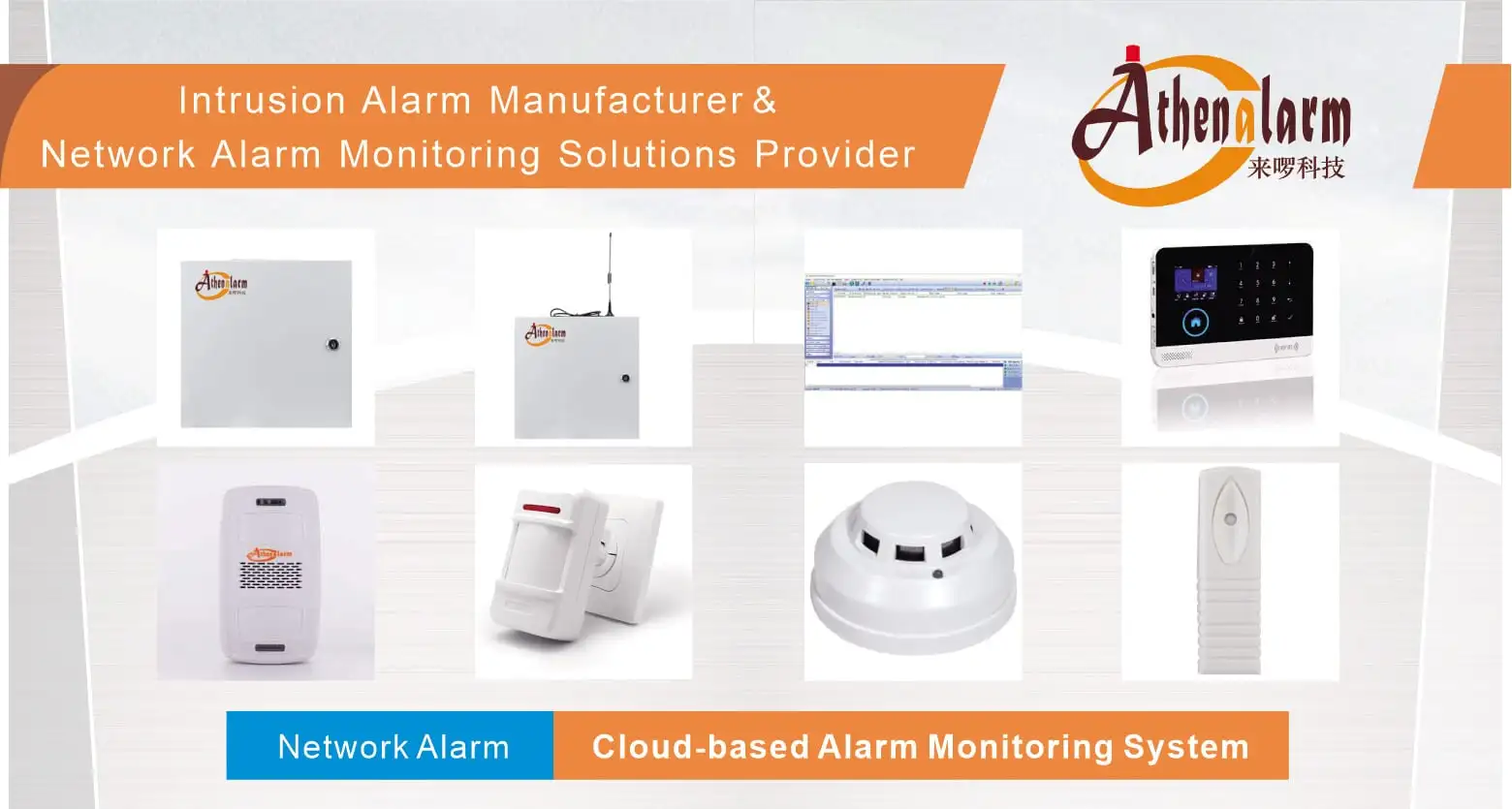
How to Avoid Intrusion Alarm System Selection and Deployment Mistakes
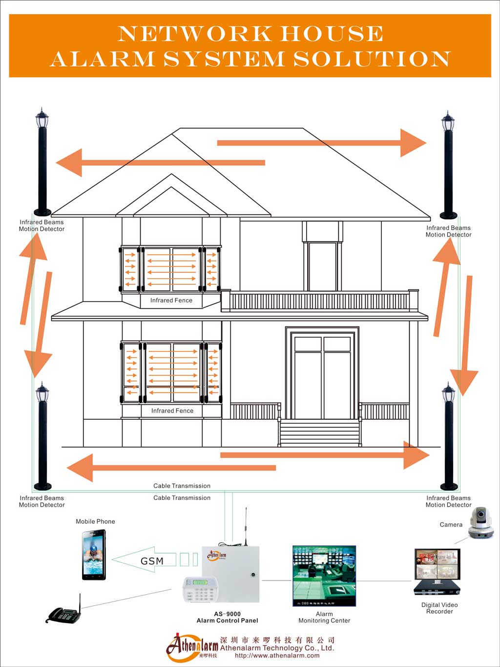
1. Start with the Intruder’s View of the Site
A site’s exposure is shaped by its entry points, operating routines, and opportunities for an intruder to approach or leave without notice. Those conditions should guide intrusion alarm system selection: the system must detect likely breaches, support a suitable response, and fit the way the site is used.
Begin by mapping doors, accessible windows, loading areas, glass, concealed approaches, and likely escape paths. Record whether doors and frames are hollow, solid wood, aluminum, or reinforced steel; note lighting, landscaping, and hiding places. Then identify when the facility is occupied, unattended, or especially vulnerable, including overnight periods, holidays, and opening and closing routines. These observations connect physical exposure to sensor coverage and arming procedures.
Deterrence, detection, verification, and response are separate functions. Deadbolts and reinforced frames increase resistance to entry. Signs and lighting may affect whether a site appears attractive to an intruder. Sensors detect activity; local sounders and lights provide immediate outputs; a Central Monitoring Station (CMS) can receive and process alarm events. Video and access-control records may add context when their interfaces and event mappings support it. No single layer guarantees prevention.
1.1 Map entry paths and sensor coverage
Choose detection devices according to the breach path and site conditions. Door/window contacts supervise openings; glass-break sensors address likely glass entry; passive infrared (PIR) and dual-technology detectors cover interior areas; a beam-based perimeter alarm architecture can support perimeter detection. Proper deployment of perimeter-secure magnetic door contacts guarantees immediate status verification at high-risk envelope boundaries, effectively preventing stealth bypass attempts. A device list alone does not establish coverage: the proposed layout must account for where an intruder could enter and move.
During the site survey, inspect construction and environmental conditions that may affect detection. Reinforced concrete, steel, low-E glass, and foil-backed insulation can attenuate or reflect wireless signals. HVAC airflow, direct sunlight, reflective surfaces, thermal changes, pests, and moving blinds can affect PIR performance. Check cellular coverage at the proposed control-panel location as well as ambient RF conditions where wireless devices will be installed.
1.2 Connect physical resistance to alarm response
Locks and door construction affect how readily an intruder can enter. The source article reports that burglars spend no more than 60 seconds defeating locks on average, and recommends deadbolts and reinforced front-door frames. Treat these measures as part of the site’s physical protection, alongside alarm detection and monitoring.
Visible security signs, surveillance, lighting, and smart-home controls can contribute to deterrence or verification. Historical studies of burglars’ responses to alarm systems and signs do not support current performance claims. A selection decision should instead define which functions are required: for example, whether an alarm input should trigger video recording, whether lighting should activate, or whether access events should be available to explain authorized entry.
1.3 Relate occupancy to arming procedures
Map staff, contractor, and visitor access against the periods when the site is armed. Opening and closing procedures affect who can disarm the system and when. If those workflows are unclear, a technically capable system can still produce user-induced alarms or remain disarmed when protection is expected.
Document the intended users, arming and disarming steps, and the roles of keypads, mobile apps, and credentials. Where an Electronic Access Control (EAC) system is present, define how door-position status and credential logs relate to alarm events. Compatibility and event mapping should be confirmed for the specific equipment.
2. Pitfall 1 — Choosing Sensors Before Assessing the Site
Sensor selection should follow a site survey. The survey connects likely entry paths to detector types, placement constraints, and wiring or wireless coverage requirements.
2.1 Match detectors to likely breach paths
Specify door/window contacts, glass-break sensors, PIR, dual-technology detectors, and beam detectors according to the areas and breach paths they need to cover. Consider the required zone behavior and whether the detection point is perimeter or interior. Avoid treating a device’s presence as proof that an entry path is monitored.
For a wireless sensor, validate the installed location rather than assuming that nominal range will hold through the building. For a hardwired sensor, plan cable routes and account for run distance and voltage drop. The control panel’s zone layout should reflect the surveyed site and the intended operational response.
2.2 Check PIR conditions before installation
PIR nuisance alarms can be associated with HVAC airflow, rapid thermal gradients, sunlight, reflective surfaces, moving pests, or fluttering blinds. Loose hinges or excessive door movement can also affect magnetic reed switches. These conditions should be checked during the survey and commissioning process.
When an indoor PIR intrusion-detection zone produces nuisance alarms, review the event history and inspect the detector’s location, field of view, sensitivity, and environmental triggers. Adjust placement or configuration where supported by the equipment; consider dual-technology validation where the design calls for it. Confirm the corrective change with a walk-test.
2.3 Validate wireless coverage or design cable routes
Concrete, metal, low-E glass, foil-backed insulation, and nearby transmitters can weaken or disrupt RF links. A weak link may lead to packet loss, delayed zone reporting, or a “Sensor Offline” supervisory fault. Check RF performance at the installed sensor and panel locations, and account for ambient interference.
| Design factor | Hardwired consideration | Wireless consideration |
|---|---|---|
| Installation | Cable route, run distance, voltage drop, and termination | Installed RF coverage and structural attenuation |
| Fault checks | Wiring continuity, supervision, and termination | Link quality, interference, and supervisory status |
| Ongoing work | Cable and device serviceability | Battery condition and RF performance |
| Expansion | Bus, zone, and power limits | Receiver capacity and validated coverage |
Use the comparison as a site-specific design prompt, not as a universal ranking. The choice depends on construction, retrofit limitations, expansion needs, maintenance capacity, and the system’s supported interfaces.
3. Pitfall 2 — Treating Locks, Signs, or Cameras as a Complete Alarm Strategy
Physical resistance, visible deterrence, detection, verification, and response contribute different functions. Selection should establish how these layers work together at the site.
3.1 Account for door and frame construction
Inspect entry-point condition before specifying alarm coverage. Deadbolts and reinforced frames can make forced entry more strenuous, while contacts and other detectors report opening or movement to the control panel. The alarm system should account for the actual door, frame, and window conditions rather than relying on a generic device schedule.
Document physical vulnerabilities alongside detector locations. This allows the system design to reflect both the entry path and the point at which alarm detection should occur.
3.2 Define what visible deterrence contributes
Lighting, landscaping, signs, and surveillance can affect whether an approach is visible and whether a property appears protected. Timed or remotely controlled lights may be operated through smart-home technology, while cameras may provide event context. These features do not replace functioning sensors or a defined monitoring path.
Avoid treating historical crime statistics as current guarantees of deterrence. Instead, document which layer performs each function and what happens when an event is detected.
3.3 Specify video and access-control interactions
A Video Management System (VMS) may start pre- or post-alarm recording, position a pan-tilt-zoom camera, or provide remote verification after an alarm input. Integration may use relay closures or SDK/API event injection. ONVIF Profile S/G/T can support inter-device video communication, but implementation and event synchronization vary by manufacturer and may require middleware.
EAC may share door-position status, credential logs, or coordinated lock behavior during duress or emergency events. Define the event mappings and compatibility requirements for the specific devices and software. A camera feed, access log, or mobile notification should not be assumed to provide the same result as a CMS receiver acknowledgment.
4. Pitfall 3 — Selecting a Panel Without Defining Resilience Needs
A hybrid intrusion alarm system combines local edge-controlled processing with cloud-connected services and CMS reporting. Engineers should integrate an enterprise-grade network alarm monitoring system solution to ensure centralized event telemetry, rapid dispatcher validation, and minimized false dispatch rates across multi-site deployments. The intrusion alarm control panel supervises zones and can execute local logic, sounders, and relay outputs even when external connectivity is severed; remote access and cloud features may depend on network or cloud availability.
4.1 Separate local functions from connected services
Identify which functions must continue during a broadband, cellular, or cloud outage. The panel’s microcontroller and real-time operating system can retain local zone monitoring and event execution, while remote control, app notifications, and cloud automation rely on their respective connections.
The control panel is also a physical dependency. If it is accessible, an intruder may attempt to suppress it before alarm transmission completes. Site design should consider the panel’s physical location and whether it is secured.
4.2 Evaluate communication paths and receiver support
Network alarm monitoring architecture can combine Ethernet or broadband IP with cellular LTE communication in a dual-path design. The architecture report identifies LTE-M/NB-IoT as cellular options and describes dual-path communication as a way to maintain signal delivery during internet outages or cut lines. Confirm the specific panel’s supported paths, failover behavior, cellular coverage, and the CMS receiver’s compatibility.
SIA DC-09 (ANSI/SIA CP-04) is a standardized IP alarm protocol that can carry Contact ID or SIA codes in UDP/TCP frames with AES encryption. MQTT and REST APIs can support cloud status, events, and control commands, but they are not identified here as certified primary life-safety alarm transmission protocols. Confirm which protocol carries each event and where it is received.
| Communication or interface | Role identified in the source | Compatibility point |
|---|---|---|
| Ethernet / IP | Alarm-event transport and connected services | Verify routing, receiver targets, and supported protocol |
| Cellular LTE | Alternate alarm communication path | Verify coverage and configured failover |
| SIA DC-09 | IP alarm-event routing to CMS | Verify encryption key, event format, and receiver support |
| MQTT / REST APIs | Cloud status, events, and commands | Use alongside the supported primary monitoring path |
| Contact ID | Legacy DTMF signaling over copper phone lines | VoIP compression can create compatibility problems |
4.3 Verify delivery to the intended receiver
An app notification does not establish that an alarm event reached the CMS. Define the intended receiver, primary and secondary IP/port targets, account and zone mapping, encryption key exchange, and expected acknowledgment. Then test the configured path end to end.
Contact ID is a legacy tonal protocol for copper PSTN lines. The system profile notes that DTMF compression on modern VoIP networks can corrupt transmissions and that PSTN networks are being decommissioned. Confirm that the receiving setup supports the selected protocol and transport rather than assuming an existing phone connection is compatible.
5. Pitfall 4 — Overlooking Wiring, Supervision, and Expansion Limits
Wiring and supervision choices affect whether a panel can distinguish expected zone states from alarm, tamper, short, or cut conditions. Installation details also determine how easily faults can be diagnosed and future devices added.
5.1 Specify EOL or DEOL configuration consistently
End-of-line (EOL) and double-end-of-line (DEOL) resistors support loop supervision. Resistance values must match the panel and detector design; examples include 2.2 kΩ, 4.7 kΩ, and 5.6 kΩ, which should not be mismatched. Incorrect values can cause false alarms or undetected zone failure.
Resistor placement matters. If a resistor is installed inside the control panel instead of at the sensor end of the line, the intended tamper protection may be defeated. When a zone reports persistent faults or erratic trips, check the specified resistor value, circuit wiring, and placement at the device.
5.2 Validate bus topology, termination, and capacity
RS485 and CAN bus connections link the panel to peripheral expanders and keypads. These connections may require differential-pair wiring, 120 Ω end-of-line termination, and a specific bus topology; star wire taps are improper for the RS485 design described. Follow the equipment requirements for the specific bus.
Expansion also depends on zone count, cable distance, and power budget. The system profile notes that additional expansion modules and remote power supplies may be needed as limits are reached. Validate the existing bus before adding devices; do not assume an installed bus can accept further loads without checking its topology and capacity.
5.3 Preserve service information
Unlabelled wiring and undocumented zones increase commissioning and future service effort. Label cable runs, record device locations and zone functions, document resistor values, and retain as-built drawings. These records make it easier to trace a line fault, verify a change, or assess expansion constraints.
The deployment profile lists structured security wire examples: 18/2, 22/4, and 22/6 AWG. Select and install wiring according to the equipment design and project requirements; these examples are not universal specifications.
6. Pitfall 5 — Ignoring False Alarms and User Workflow
False alarms can begin with environmental conditions, installation choices, or operating procedures. Their consequences may include CMS workload, law-enforcement dispatch, municipal fines, reduced dispatch priority, service visits, and customer attrition, as described in the engineering friction analysis.
6.1 Trace nuisance alarms to their source
For a recurring PIR alarm, check airflow, thermal changes, sunlight, reflective surfaces, pests, and moving blinds. For a door contact alarm, inspect hinge movement and reed-switch alignment. Review the zone’s history and test the suspected condition before changing configuration.
Where the environment is incompatible with the detector’s placement, adjust placement or supported settings. A dual-technology detector may be considered where suitable. Verify any corrective action through a walk-test and confirm that the zone still detects the intended event.
6.2 Set entry and exit delays around real routines
Entry and exit delays should fit actual opening, closing, and staff movement. A delay that is too long increases the time before an alarm response; one that is too short can trigger user-induced false alarms. Account for authorized access and staff turnover when defining zone types and procedures.
The deployment profile identifies Entry/Exit, Perimeter, Interior Follower, and 24-hour Silent Panic as zone types to define during programming. It also identifies delay timers and output relays as commissioning tasks. Configure these according to the required site workflow and equipment behavior.
6.3 Define verification and escalation
Specify the centralized alarm-event management interface, how it presents alarm details, and what action staff should take. Compatible, properly configured video, access-control logs, and alarm data can help staff assess an event. Explain how local sounders, remote notifications, and central monitoring workflows work together.
Document alarm handling and false-alarm procedures according to local requirements. False alarms may lead to municipal fines or changes in emergency-response priority, depending on local rules. Confirm the requirements that apply to the site.
7. Pitfall 6 — Comparing Purchase Price Without Lifecycle Cost
Initial equipment and installation costs do not capture the work required to keep an intrusion alarm system operational. Compare options across power, communications, service, maintenance, and expansion needs over the intended lifecycle.
7.1 Compare hardwired and wireless maintenance needs
Hardwired and wireless designs have different installation and maintenance constraints. Hardwired designs require cable planning and termination; wireless designs require validated RF coverage and ongoing sensor-battery attention. Building construction and retrofit conditions influence which approach is practical.
The system profile lists SLA (Sealed Lead-Acid) and LiFePO4 batteries as backup power options. It also states that local battery backup guarantees 24–48 hours of continuous operation during power failure. Treat that figure as profile-specific: actual performance depends on system load, battery condition, and configuration, which should be checked for the selected installation.
7.2 Include recurring costs and service capacity
Include battery replacement, cellular subscriptions, platform fees, service visits, and false-alarm handling in the comparison. Account for the maintenance effort needed to monitor battery degradation, RF link performance, and firmware synchronization between panels, cloud bridges, and CMS receivers.
System expansion may require field-bus zone expanders, wireless receivers, or panel-to-panel network integrations. Confirm the panel’s capacity and the cost of additional modules or remote power supplies before committing to a design. Avoid evaluating only the initial device price when recurring service and expansion needs are material to operations.
7.3 Check standards and compatibility before procurement
Confirm local requirements and project-specific standards before selection. The deployment profile names EN 50131 Grade 2/3 and UL 1023/611 as examples of standards that may be relevant; applicability depends on jurisdiction and use case. The profile also describes ONVIF Profile S/G/T for video integration and SIA DC-09 for IP alarm reporting.
Verify compatibility among the control panel, detectors, firmware, CMS receiver, VMS, and EAC.
8. Use a Pre-Procurement and Commissioning Checklist
A selection is ready for acceptance when the site risks, system configuration, communication paths, and operating responsibilities have been documented and tested.
8.1 Before selection
- Map entry and exit paths, concealed approaches, door and frame construction, occupancy patterns, and vulnerable periods.
- Record environmental constraints, including HVAC airflow, direct sunlight, reflective surfaces, RF noise, and structural barriers.
- Identify required sensor coverage, hardwired routes or wireless locations, expansion plans, and panel placement.
- Define which alarm functions must operate locally during network or cloud outages.
- Specify monitoring requirements, communication paths, receiver support, and required event acknowledgment.
- Compare backup power, cellular and platform fees, battery maintenance, service capacity, and false-alarm handling.
- Confirm applicable standards and product compatibility for the jurisdiction and project.
8.2 Before handover
- Walk-test every zone and verify the intended detection and local outputs.
- Test Alarm, Restore, Tamper, Low Battery, and AC Loss events as applicable.
- Verify primary and secondary receiver targets, event and zone mapping, encryption key exchange, and receiver acknowledgment.
- Confirm cellular and IP communication behavior and the configured failover path.
- Check EOL/DEOL values and placement, bus topology and termination, and documented wiring.
- Review user arming and disarming workflows, entry and exit delays, and alarm escalation procedures.
- Provide zone records, device locations, cable labels, as-built drawings, and maintenance responsibilities.
9. FAQ
Q1: How should a business choose between hardwired and wireless intrusion sensors?
Choose according to construction, cable routes, RF coverage, retrofit constraints, expansion needs, and maintenance capacity. Hardwired systems require wiring and termination planning; wireless systems require on-site RF validation and ongoing battery attention.
Q2: What should a site survey identify before an intrusion alarm is specified?
A site survey should identify entry paths, occupancy patterns, door and frame construction, environmental conditions, RF noise, cellular coverage at the panel location, and cable-route constraints. Those findings guide sensor selection and communication design.
Q3: What is the benefit of local alarm processing if a cloud service or internet connection fails?
Local processing can preserve panel logic, zone monitoring, sounders, and relay outputs when external connectivity is lost. Remote access, app functions, and cloud services may depend on network availability.
Q4: When is dual-path IP and cellular alarm communication appropriate?
Consider it when the site’s monitoring requirements and outage risks justify redundant communication and the panel, cellular coverage, and CMS receiver support the configured paths. Confirm failover behavior and recurring costs.
Q5: How can a team confirm an alarm event reached its monitoring station?
Run end-to-end tests for the required zones and event types, verify receiver configuration and event mapping, and confirm the expected CMS receiver acknowledgment. An app notification alone does not confirm CMS receipt.
Q6: Why does EOL resistor placement matter in an intrusion alarm zone?
The specified value and placement determine how the panel supervises the loop. A resistor installed in the panel rather than at the sensor end can defeat intended tamper supervision; follow the detector and panel design.
Q7: What causes PIR motion detector false alarms in commercial buildings?
HVAC airflow, rapid thermal changes, direct sunlight, reflective surfaces, pests, and moving blinds can contribute. Check the detector’s location and environment, then validate any adjustment with a walk-test.
Q8: How should wireless sensor coverage be checked in a building with concrete or metal construction?
Validate RF performance at the installed sensor and panel locations. Concrete and metal can attenuate or reflect signals; if coverage is inadequate, revise placement or evaluate a hardwired route or supported expansion option.
Q9: What should be included in an intrusion alarm commissioning test?
Test every zone and applicable Alarm, Restore, Tamper, Low Battery, and AC Loss events. Verify communication paths, receiver mapping, encryption key exchange, and acknowledgment, then document wiring, devices, and user workflows.
Q10: Which recurring costs should be included when comparing intrusion alarm systems?
Include backup battery replacement, cellular subscriptions, platform fees, service visits, false-alarm handling, and maintenance for wireless sensors and RF links. Compare these costs with the system’s expansion and service requirements.
