

Perimeter Protection and Intrusion Alarm Integration for Critical Infrastructure
1. Why Perimeter Protection Has Become an Engineering Discipline
The operational failure mode that exposes critical infrastructure most persistently is not a sophisticated cyberattack or coordinated physical assault—it is the slow degradation of detection confidence caused by poorly integrated sensor architectures that were never designed to interoperate at scale. A thermal camera that cannot communicate its classification output to a PTZ camera without manual operator relay. A ground radar node streaming coordinates in a proprietary format that the Video Management System cannot parse natively. An alarm event transmitted over an unencrypted legacy path that fails NERC CIP audit requirements. Each of these represents an engineering gap, and in aggregate, they create a perimeter that reacts rather than responds.
Perimeter protection for critical infrastructure—energy substations, data centers, water treatment facilities, airports, and logistics hubs—has evolved from a passive boundary control function into an active, multi-layered engineering discipline. The threat model driving this evolution is not theoretical. State-sponsored actors targeting power grid infrastructure, organized criminal groups executing precision copper theft operations at remote substations, and insider-assisted intrusions at logistics facilities all demand detection, verification, and deterrence systems that operate with architectural coherence rather than component-level independence.
The engineering challenge is not procurement of capable individual sensors. When sourcing these specialized hardware components, collaborating with an experienced burglar alarm manufacturer ensures that edge devices maintain structural resilience and hardware-level protocol alignment. Ground Surveillance Radar, uncooled thermal imaging, AI-powered video analytics, and PTZ cameras with sub-second slew rates are all commercially available. The engineering challenge is binding these detection technologies into a unified Perimeter Intrusion Detection System (PIDS) where radar coordinate vectors flow directly into PTZ steering matrices, where thermal classification outputs trigger edge-local deterrence loops without cloud round-trips, and where every alarm event carries a cryptographically protected audit record before it reaches a Central Monitoring Station.
This whitepaper addresses that engineering problem with operational depth: system architecture and functional boundaries, end-to-end detection workflows, protocol stack analysis, deployment realities including grounding and fiber infrastructure, engineering friction encountered at scale, system trade-offs affecting procurement decisions, lifecycle management, compliance anchoring, and scenario-specific configuration guidance.
2. What Is an Integrated Perimeter Intrusion Detection System (PIDS)?
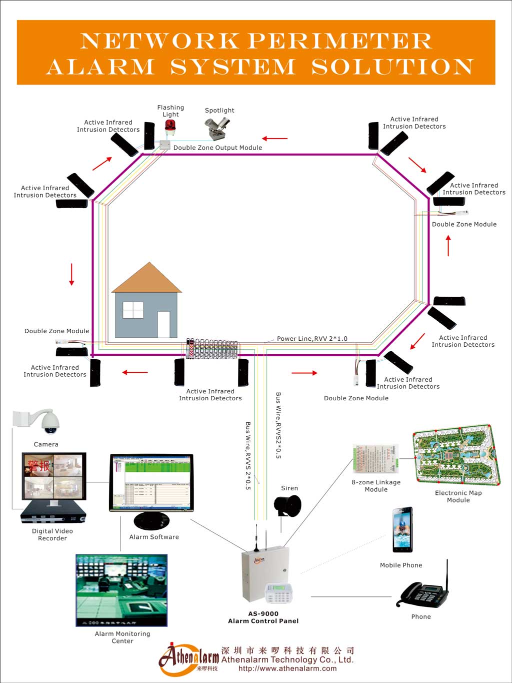
An integrated network perimeter alarm system solution (PIDS) is a structured, multi-layer physical security platform designed to continuously monitor, classify, verify, and respond to threats at the physical boundaries of a protected facility. A PIDS is not a collection of independent sensors managed through separate interfaces—it is an integrated control architecture in which each component contributes to a coordinated detection-to-response chain.
The physical boundary of a PIDS extends beyond the fence line itself. Ground Surveillance Radar coverage begins in the outer exclusion zone, reaching targets at extended range before they contact any physical barrier. The fence line represents the second containment layer. The sterile zone—the corridor between the outer perimeter fence and internal facility structures—functions as the final boundary where delayed response can still intercept a breach. These spatial layers map directly onto the PIDS functional architecture.
The functional architecture of an integrated PIDS consists of four operational layers:
The Detection Layer captures raw threat signals. Ground Surveillance Radar, thermal imaging cameras, fiber-optic fence vibration sensors, and AI video analytics cameras all operate at this layer, each contributing different signal types—motion vectors, heat signatures, vibration frequency data, and optical classifications—to the overall detection matrix.
The Verification Layer correlates and validates raw detection signals to distinguish real intrusion events from environmental triggers. PTZ cameras executing Slew-to-Cue positioning, AI analytics engines classifying objects against behavioral baselines, and multi-sensor fusion logic combining radar coordinate data with thermal imaging confirmation all function within this layer.
The Deterrence and Delay Layer executes active responses. IP horn speakers delivering live or pre-recorded voice warnings, trigger-activated strobe lighting, and automated gate lockdowns through Physical Access Control Systems (PACS) all operate here, introducing both psychological and physical barriers to intrusion progress.
The Command and Monitoring Layer aggregates all event data, video streams, and alarm records into a centralized Video Management System (VMS) or Physical Security Information Management (PSIM) platform. This layer serves as the core network alarm monitoring system solution, ensuring that localized situational updates are synchronized instantly across the enterprise network. This layer generates the audit trail, routes verified alerts to Central Monitoring Stations (CMS), and provides the operator interface for real-time situational awareness.
The logical boundary of a PIDS ends at the edge interface of the broader network alarm system—the switch, router, or cellular gateway that separates edge Operational Technology (OT) from centralized Information Technology (IT) networks. This boundary is architecturally significant: everything on the field side of this interface must maintain operational autonomy sufficient to sustain detection and deterrence functions during network connectivity loss.
3. Core Operational Workflow of Modern Perimeter Protection
The operational workflow of an integrated PIDS follows a sequential engineering chain. Each stage depends on the output of the preceding stage, and failures at any single point degrade the integrity of the entire response sequence.
Detection initiates when a sensor at the Detection Layer captures a signal exceeding its configured threshold. A Ground Surveillance Radar node detects a moving target in the outer exclusion zone and begins streaming azimuth, distance, and velocity telemetry to the VMS Processing Engine via MQTT protocol. Simultaneously, thermal imaging cameras monitoring the same zone register a heat signature consistent with a human-scale target.
Sensor Fusion combines these independent data streams. The VMS Processing Engine correlates the radar-derived geospatial coordinates—expressed as X, Y position vectors—with the thermal camera’s spatial field of view. When both data streams converge on the same target position within a defined time window, the system’s confidence in a real detection event increases substantially, reducing the probability of a false alarm from either sensor operating in isolation.
Threat Verification follows confirmed sensor fusion. The VMS engine issues a Slew-to-Cue command to the nearest PTZ camera, transmitting pan, tilt, and zoom coordinates derived from the radar tracking matrix via ONVIF Profile T commands or manufacturer-specific API. The PTZ camera reorients to the target within the sub-100 ms latency window achievable by edge-local processing architectures, and AI video analytics running on the camera or edge appliance classify the object—distinguishing a human from wind-blown foliage, a vehicle from a large animal, or a crawling intruder from ground-level vegetation movement.
Automated Deterrence activates upon positive verification. The Local Deterrence Controller receives a trigger command from the analytics camera via Modbus TCP, HTTP POST command, or dry-contact relay closure. A high-intensity physical warning light activates, an IP horn speaker broadcasts a pre-recorded voice warning, and the event is tagged with geospatial metadata and timestamped for logging.
Delay Mechanisms engage when detection confidence exceeds the defined threshold for a physical breach. The PACS platform receives a gate lockdown command routed through the CMS or directly from the local alarm control panel, sealing vehicle and personnel access points within the relevant perimeter zone. Simultaneously, an industrial-grade door contact verifies the physical closure status of the gate to guarantee containment integrity. Mobile security patrols receive geo-tagged alerts on their devices, directing response to the breach coordinates.
Evidence Collection runs continuously throughout this chain. HD and thermal video streams are archived to edge storage nodes and synchronized to the central VMS Storage Engine. Every alarm event carries GIS-mapped coordinates, camera identifiers, and detection timestamps. Biometric data—where facial recognition or voice capture systems are deployed—augments the forensic record.
Incident Reporting closes the workflow. Verified alarm events are transmitted from the VMS Storage Engine to the CMS via the SIA DC-09 protocol encrypted with AES-128 or AES-256. The CMS platform, powered by advanced network alarm center management software, logs the event, triggers response dispatch workflows, and creates the compliance-ready audit record required for NERC CIP Version 5/6 internal audits and CISA physical asset security evaluations.
4. Detection Technologies and Their Operational Roles
Ground Surveillance Radar (GSR) forms the outermost detection boundary in most critical infrastructure deployments. GSR operates in the 24 GHz or 77 GHz frequency bands, detecting moving targets beyond physical barriers and across terrain that optical cameras cannot monitor—undulating ground, dense low-level vegetation, and water-adjacent terrain where fence installation is impractical. Radar outputs continuous azimuth, range, and velocity data, enabling the VMS engine to build a real-time positional track of any detected target before it reaches the perimeter fence. The operational limitation of GSR is signal attenuation: heavy precipitation, particularly rain or dense fog, attenuates radar returns in both the 24 GHz and 77 GHz bands, reducing effective tracking range and temporarily lowering the system’s Probability of Detection (P_d). This is not a failure of the technology but a physical constraint requiring compensating sensor layers.
Thermal Imaging Cameras detect infrared radiation emitted by human bodies, vehicles, and heat-generating equipment, independent of visible light conditions. Thermal cameras function reliably in complete darkness, fog, smoke, light rain, and conditions where optical cameras produce unusable images. Uncooled thermal detectors are the dominant technology in critical infrastructure deployments, offering long operational life, reasonable cost, and sufficient sensitivity for perimeter-range classification. Thermal imaging cannot distinguish facial features or read license plates—its classification output remains relatively coarse—but its ability to detect human-scale heat signatures through fog or at extended night ranges makes it the primary sensor technology for detection in adverse environments. Pairing uncooled thermal cameras with GSR produces a dual-layer detection system that maintains P_d during most severe weather conditions that would blind visible-light cameras entirely.
Visible AI Video Analytics Cameras deliver the classification depth that thermal imaging cannot. AI analytics engines running on edge appliances or embedded camera chips apply object classification models trained to differentiate humans, vehicles, animals, and environmental triggers based on shape, motion patterns, trajectory, and behavioral signatures. A human crawling slowly across a field presents a very different motion signature than wind-blown vegetation or a running deer, and well-trained analytics models exploit these differences to suppress nuisance alarms. The limitation of visible analytics is light-dependency—performance degrades in low-light conditions without supplemental illumination—and sensitivity to weather effects including heavy rain and fog that blur optical clarity. AI analytics cameras function most effectively as the verification layer rather than the primary detection layer.
Virtual Fencing uses detection technologies—typically radar, thermal imaging, or fiber-optic cable—to define monitored boundary zones without requiring physical barriers. Virtual fences are particularly valuable in riverbank environments, water-adjacent terrain, or expansive remote sites where physical fencing is structurally impractical or economically prohibitive. Thermal virtual fences establish geofenced detection zones that trigger the same alarm and deterrence workflows as a physical fence breach. The engineering consideration is zone calibration: virtual fence boundaries must be precisely mapped against the GIS layout within the VMS, and their detection thresholds must be tuned to suppress persistent environmental triggers in the vicinity—water surface movement, for example—without degrading sensitivity to genuine intrusions.
Multi-Sensor Correlation is not a discrete technology but an architectural function that determines whether the preceding technologies deliver a coherent detection picture or a fragmented collection of independent alerts. When radar geospatial data, thermal classification output, and visible AI analytics metadata are routed to a common VMS Processing Engine that applies configurable fusion logic—requiring, for example, two-of-three sensor types to report on the same target within the same spatial zone within a defined time window—the system’s false alarm rate drops significantly while detection confidence for genuine threats increases. Multi-sensor correlation is the technical mechanism that converts individual sensor performance specifications into real-world P_d values at the perimeter level.
5. System Architecture Behind Modern Perimeter Protection
The architecture underlying a modern integrated PIDS must address a fundamental operational requirement: critical detection and deterrence functions must continue operating even when network connectivity to the central head-end is disrupted. This requirement drives the adoption of hybrid edge-cloud architectures as the dominant design pattern for industrial-grade perimeter security.
Edge Processing Architecture places AI analytics inference, radar tracking algorithms, and Slew-to-Cue input/output control loops on hardened field appliances co-located with sensors at perimeter nodes. Each perimeter node—typically comprising a network switch, GSR unit, PTZ camera, thermal camera, and audio deterrence horn—operates as a functionally autonomous unit. The edge appliance executes detection, verification, and deterrence sequences entirely within the local hardware stack, without requiring a round-trip to a centralized server for any time-critical decision. This architecture enables Slew-to-Cue loop execution latencies below 100 ms—an operationally significant figure, as a target moving at walking pace can cover several meters during a 30-second manual verification delay.
Edge processing introduces its own engineering constraints. Each field node requires industrial-grade compute hardware capable of running AI inference workloads under the temperature, humidity, and vibration conditions present at outdoor perimeter sites. This hardware is expensive relative to generic IP cameras, increasing capital expenditure per node. Edge devices are physically accessible to adversaries, requiring tamper detection sensors, cryptographic module integration, and physical port security at the enclosure level. Firmware management across dozens of distributed edge nodes—each requiring individually validated software updates without disrupting active alarm pipelines—creates sustained operational complexity.
Server-Side Analytics Architecture centralizes AI inference on rack-mounted compute nodes within the facility’s core data room or a secured private cloud environment. Camera nodes stream raw HD video to the central server, where analytics processing occurs. This reduces per-camera hardware cost and simplifies analytics model updates—changing a classification threshold or adding a new detection zone requires a single server-side configuration change rather than firmware deployment to every field node. The architectural vulnerability is a single point of failure: if the network path between field cameras and the analytics server is severed, the entire analytics layer stops functioning. For a facility where fiber backhaul runs along a fence line vulnerable to the same physical attack scenario the system is designed to detect, this is a material operational risk.
Hybrid Edge-Cloud Architecture distributes processing responsibilities based on latency criticality. Time-critical loops—Slew-to-Cue targeting, local deterrence activation, edge video storage—execute on field appliances. Configuration management, global threat pattern analysis, long-term archival storage, and compliance reporting execute on the centralized head-end server array or secured private cloud. The PSIM framework sits above this architecture as the integration layer that aggregates alarm events, provides a unified operator interface, and manages dispatch workflows across all facility security subsystems.
System Survivability During Network Failures is an explicit design requirement in critical infrastructure deployments. When the primary fiber backhaul is cut—whether by equipment failure, environmental damage, or deliberate sabotage—edge nodes must continue tracking targets, logging video to local SD card or edge storage, activating local deterrents, and maintaining gate lockdown states. Dual-homed backhaul links combining a primary single-mode fiber ring with 4G/5G LTE cellular failover provide telemetry persistence during main-line failures. This dual-homed approach ensures that alarm event transmission to the CMS via SIA DC-09 continues even during catastrophic fiber cuts, maintaining the continuous monitoring obligation required under critical infrastructure security frameworks.
6. Communication Protocols and System Integration
The protocol stack governing communication between PIDS components determines the speed, security, and interoperability of the integrated system. Each protocol in the stack serves a defined function, and the interactions between protocols—including their limitations—have direct operational consequences.
SIA DC-09 (TCP/IP) transmits structured alarm event codes from edge controllers to Central Monitoring Station receivers over IP networks. SIA DC-09 has replaced legacy analog PSTN transmission as the dominant alarm signaling protocol in industrial deployments. Its operational significance for critical infrastructure compliance lies in its support for cryptographic wrapping: alarm events transmitted via SIA DC-09 can be encrypted with AES-128 or AES-256, creating tamper-evident transmission records that satisfy NERC CIP Version 5/6 audit trail requirements. Each event code carries zone identification, event type, and timestamp, providing the structured data that CMS platforms require to route alarm verification and police dispatch workflows.
ONVIF Profile S, G, T, and M provide the standardization layer that enables multi-vendor device integration within the VMS framework. Profile S handles basic video streaming; Profile G manages edge storage retrieval for post-event review; Profile T handles advanced H.264/H.265 video stream configurations supporting high-definition thermal and visible imaging; Profile M standardizes analytics metadata streaming, including object classification bounding boxes and geospatial coordinates. The operational limitation of Profile M in PIDS environments is that it does not completely standardize raw geospatial radar point-cloud data formats. Deployments utilizing a robust enterprise alarm monitoring system integrating GSR units from manufacturers with proprietary tracking algorithms require manufacturer-specific SDK integrations or supplemental MQTT messaging paths to ensure accurate real-time radar-to-PTZ tracking matrices.
MQTT (Message Queuing Telemetry Transport) functions as the lightweight telemetry protocol streaming continuous target metadata—X, Y coordinate vectors, velocity, azimuth—from radar nodes to the VMS Processing Engine. MQTT’s publish-subscribe architecture and minimal protocol overhead make it well-suited for low-bandwidth or intermittently connected wireless mesh backhaul paths. Ground Radar Node → VMS Processing Engine data flows via MQTT or proprietary manufacturer SDK over TCP/IP, delivering the positional data that the Slew-to-Cue automation loop depends on for PTZ targeting accuracy.
Modbus TCP and Industrial Digital I/O provide the ultra-fast command path between edge analytics devices and local deterrence controllers. When an analytics camera validates a detection event, it closes an electrical output contact or sends a Modbus TCP command to the deterrence controller, which activates strobe lighting, sirens, or gate lockdowns. Modbus TCP lacks inherent encryption or authentication in its standard implementation. Any deployment routing Modbus TCP over shared network segments must enforce strict VLAN isolation to prevent internal network actors from injecting false commands or intercepting control traffic.
RTSP/RTP (Real-Time Streaming Protocol / Real-Time Transport Protocol) delivers HD video and thermal imaging streams alongside two-way audio to operator consoles. The protocol-level decision between TCP and UDP transport has direct operational consequences in PIDS environments. RTSP over TCP enforces packet recovery through retransmission loops, ensuring complete frame delivery but introducing latency spikes and stream freezing on congested or high-loss network paths. RTSP over UDP prioritizes real-time frame delivery, accepting occasional minor packet loss in exchange for consistent low-latency streaming. For Slew-to-Cue automated target tracking, where spatial accuracy and temporal precision matter more than recovering dropped pixels, RTSP over UDP is the operationally preferred configuration.
Protocol Selection Trade-offs reflect the competing requirements of the PIDS protocol stack. High-bandwidth video transport (RTSP/RTP) demands reliable, high-throughput network paths. Lightweight telemetry (MQTT) tolerates low-bandwidth and intermittent connectivity. Alarm signaling (SIA DC-09) requires encrypted, authenticated transmission with delivery confirmation. Control commands (Modbus TCP) require ultra-low latency but carry security vulnerabilities that demand network-level isolation. Designing a protocol stack that satisfies all four requirement profiles simultaneously across a multi-kilometer perimeter with mixed wired and wireless backhaul segments is one of the core integration engineering challenges in PIDS deployment.
7. Deployment Engineering Considerations
Site Survey and Terrain Analysis establish the engineering parameters that determine sensor placement, coverage geometry, and infrastructure routing before any hardware is procured. The core deliverable of a site survey is a sensor coverage model that identifies the radar line-of-sight paths, camera field-of-view geometry, RF spectrum availability for wireless backhaul, and environmental factors—seasonal vegetation growth, water body proximity, prevailing wind patterns—that will influence both detection performance and false alarm rates throughout the system’s operational life.
Terrain blind spots present the most consequential site survey risk. Undulating elevation changes, berms, drainage channels, or dense tree lines can create gaps in GSR coverage where targets approach the fence line undetected. Identifying these blind spots during the survey phase allows engineers to adjust sensor placement or specify overlapping coverage zones. Failing to identify them during design forces post-installation change orders that can significantly expand project budgets and delay commissioning.
Fiber Infrastructure is the preferred backhaul medium for PIDS installations requiring high bandwidth, low latency, and immunity to electromagnetic interference. Single-mode fiber optic cable, routed in conduit within protective trenches, supports the high-bandwidth video streams from thermal and HD visible cameras while maintaining near-zero latency for Slew-to-Cue control loops. ERPS (Ethernet Ring Protection Switching) ring topologies provide automatic failover if a fiber segment is severed, rerouting traffic around the break within milliseconds.
A recurring installation failure mode is fiber micro-bending. When single-mode fiber is pulled through conduit with insufficient attention to minimum bend radius—a constraint that is easy to violate when pulling cable around corners in buried conduit, through cable tray transitions, or over pole mounting brackets—micro-bends form within the glass core. These micro-bends cause signal attenuation that is not always immediately detectable during installation testing but manifests as intermittent packet loss under high traffic loads, degrading video stream quality precisely during high-event periods when bandwidth demand peaks. Specifying conduit bend radius minimums in installation contracts and performing optical time-domain reflectometer (OTDR) testing on every fiber run after installation are standard mitigation practices.
Wireless Mesh Backhaul serves deployments where fiber trenching is cost-prohibitive or physically impractical—remote substations, expansive agricultural perimeters, or sites with geotechnical constraints. Wireless mesh networks using ruggedized outdoor access points provide flexible coverage, fast deployment timelines, and the ability to route around node failures through mesh re-convergence. The operational vulnerabilities are RF interference susceptibility, atmospheric signal attenuation during severe weather, and the theoretical risk of RF jamming by sophisticated adversaries. Dual-homed configurations combining wireless mesh with 4G/5G LTE cellular gateways address the reliability gap for critical infrastructure applications.
Grounding and Electrical Protection govern the survivability of perimeter electronics in environments exposed to lightning, electrical transients, and EMI from high-voltage infrastructure. The objective is single-point grounding: every metal enclosure, cable shield, and equipment chassis along the perimeter bonds to a common low-impedance ground reference, preventing ground loops from forming between components at different electrical potentials.
Achieving low-resistance grounding in rocky or dry soil presents a recognized field challenge. High-resistance substrate—found at many remote substation sites where soil moisture is minimal and stone is close to the surface—limits the effectiveness of standard ground rods and requires supplemental grounding techniques such as ground enhancement compounds, extended electrode arrays, or chemical grounding electrodes. Poorly grounded copper communication lines running adjacent to high-voltage switchgear fencing are vulnerable to voltage induction from electromagnetic transients, which can destroy RS-485 driver chips, copper switch ports, and camera power supplies in a single surge event.
Power Redundancy at remote and off-grid perimeter nodes requires localized energy storage sized to maintain full edge-node operation through extended grid outages. Solar arrays paired with Lithium Iron Phosphate (LiFePO₄) battery storage are the dominant off-grid power architecture for remote PIDS nodes. LiFePO₄ chemistry provides higher cycle life, improved thermal stability, and better performance at temperature extremes compared to conventional lead-acid alternatives. UPS systems at wired sites provide short-duration ride-through capability during grid interruptions, with sizing based on the full load of the perimeter node electronics and the required hold-up duration specified in the facility’s SLA framework.
8. Engineering Friction That Reduces System Performance
High False Alarm Rate (FAR) and Nuisance Alarm Rate (NAR) are the most operationally disruptive engineering friction sources in deployed PIDS environments. FAR and NAR measure the frequency with which the system generates alerts triggered by non-threatening stimuli rather than genuine intrusion events. Wind-blown vegetation moving rhythmically across a radar detection zone, wildlife—deer, birds, or large rodents—crossing a thermal virtual fence line, and solar reflections off water surfaces near riverbank installations all generate detection signals that a poorly configured system will process as alarm events.
The operational consequence of sustained high FAR is not merely inconvenience. Operators confronted with hundreds of nuisance alarms per shift develop alert fatigue, reducing their response rate to genuine events. VMS event logs become saturated with low-value records, obscuring legitimate intrusion signatures during post-event forensic review. Central Monitoring Stations that receive excessive nuisance alarms from a site may apply contractual penalization fees or, in severe cases, refuse to continue monitoring service. The business consequence is a security system that is nominally operational but practically unreliable.
Mitigation requires multi-layered approaches. Multi-sensor correlation—requiring both radar and thermal confirmation before generating an alert—eliminates single-sensor nuisance triggers. AI analytics classification filters distinguish human and vehicle motion signatures from environmental movement patterns. Dynamic analytical masking suppresses detection in known high-nuisance zones—a water surface visible to a thermal camera, or a tree line that sways consistently in prevailing wind—during defined time windows or weather conditions. Software-defined detection delay algorithms introduce a brief time buffer before alarming, filtering out transient movements that do not persist long enough to represent a genuine intrusion.
Signal Attenuation and Environmental Interference degrade detection performance through physical mechanisms that cannot be entirely eliminated by system configuration. Heavy precipitation attenuates radar signals in the 24 GHz and 77 GHz bands, reducing effective tracking range and temporarily lowering P_d during severe weather events. Dense fog reduces the operational range of both visible and thermal cameras. These are not failure modes but predictable performance constraints that inform sensor selection and coverage overlap design. Deploying dual-sensor thermal cameras with integrated visible and thermal imaging on the same optical path, and specifying GSR units in lower frequency bands less sensitive to precipitation attenuation where threat models require all-weather coverage, are the procurement-level responses to these constraints.
Electrical Transients and Ground Loops cause physical hardware damage that is costly to diagnose and repair. Lightning strikes on or near perimeter structures induce high-voltage transients through copper communication cables, destroying connected electronics at both ends of the cable run. Ground loops—formed when two pieces of equipment connected by a cable have different electrical ground potentials—generate continuous low-level noise that degrades RS-485 serial communication, causes video interference, and can damage sensitive electronic components over time. Both failure modes share a common root cause: inadequate or inconsistent grounding infrastructure. Specifying fiber optic communication paths between field enclosures eliminates the conductive ground loop path entirely, as fiber carries no electrical current and is immune to both lightning induction and ground potential differences.
Firmware Drift and API Incompatibilities emerge as long-term operational risks rather than immediate deployment failures. Critical infrastructure PIDS installations have operational lifetimes measured in decades. Over that lifespan, VMS platform software will receive multiple major version updates, edge device manufacturers will release firmware revisions addressing security vulnerabilities, and the API interfaces between these software layers will evolve. When a VMS platform undergoes a major version upgrade without coordinated, validated updates to the firmware APIs of every connected edge device, the result is broken integration loops. Custom analytics metadata pipelines stop delivering classification data to the VMS engine. Slew-to-Cue automation workflows execute positioning commands against outdated coordinate translation matrices, causing PTZ cameras to aim at incorrect locations when tracking fast-moving targets. The ONVIF Profile M analytics metadata stream from a camera firmware version may use different bounding box data structures than the updated VMS platform expects, silently discarding object classification data.
The direct consequence of firmware drift in critical infrastructure contexts is cyber-security exposure. If a VMS platform update that patches a known critical vulnerability breaks the edge device integration, operators face a difficult choice: apply the security patch and accept broken Slew-to-Cue functionality until firmware updates are validated, or defer the security patch to preserve operational continuity, leaving the platform vulnerable. Implementing multi-phase firmware validation testing environments that mirror production configurations before applying any updates to live infrastructure is the standard operational discipline for managing this risk.
Pole Whip is a structural failure mode specific to perimeter installations that is rarely discussed in vendor documentation but well-known to experienced field engineers. Slender camera or radar mounting poles subjected to sustained wind loads develop oscillatory vibration—the pole deflects and returns in a resonant cycle that slightly but consistently shifts the sensor’s physical aim point. For a radar unit mounted on a pole experiencing pole whip, the coordinate tracking grid—calibrated against fixed reference points during commissioning—drifts over time as the physical sensor position oscillates. The resulting effect is a progressive positional offset in the radar-to-PTZ tracking matrix: the PTZ camera steers to a location displaced from the actual target position, degrading verification accuracy without generating any obvious system error. Scheduled pole bracket inspection and tightening, combined with periodic radar tracking matrix recalibration against fixed reference targets, are the maintenance responses to this failure mode.
9. Engineering Trade-Offs
Wired versus Wireless Network Backhaul presents the most financially significant trade-off in PIDS infrastructure planning. Single-mode fiber optic ring infrastructure delivers high bandwidth sufficient for multi-stream HD and thermal video, near-zero latency compatible with sub-100 ms Slew-to-Cue loops, complete immunity to EMI and RF jamming, and long-term reliability with maintenance costs limited to connector cleaning and occasional OTDR validation. The capital cost is dominated by trenching, conduit installation, and fiber termination labor—expenses that scale linearly with perimeter length and can reach substantial figures for multi-kilometer perimeters in difficult terrain. Wireless mesh or LTE cellular backhaul eliminates trenching costs, accelerates deployment timelines, and provides viable coverage for sites where trenching is geotechnically impossible. The operational trade-offs are susceptibility to atmospheric signal attenuation during severe weather, vulnerability to RF interference from nearby industrial equipment, and—for high-security sites—the theoretical risk of signal jamming by sophisticated adversaries targeting the communication infrastructure rather than the perimeter itself.
Edge AI versus Server-Side AI Video Analytics determines where computational intelligence resides within the system architecture, with direct consequences for latency, survivability, cost, and maintenance complexity. Edge-inference architectures execute classification algorithms on field-hardened compute appliances, enabling Slew-to-Cue loop completions below 100 ms without any network round-trip to a central server. If the backhaul network fails, edge nodes continue detecting, classifying, and responding autonomously—a survivability characteristic critical for sites where the network and the physical perimeter may be attacked simultaneously. Server-side analytics architectures lower per-camera hardware costs and simplify analytics model management—deploying an updated classification model to a server changes the behavior of every connected camera simultaneously, while the equivalent edge-side operation requires orchestrated firmware deployment to dozens of individual field devices. The server-side vulnerability is the creation of a network-dependent single point of failure in the detection chain.
Sensor Sensitivity versus Nuisance Alarm Rate represents the fundamental operational trade-off in detection system configuration. Maximum sensitivity (P_d → 1.0) minimizes the risk of missed detections—particularly for stealthy low-signature threats such as slowly crawling intruders or targets exploiting foul weather for concealment—but generates elevated nuisance alarm rates from environmental movement. Aggressive analytical filtering suppresses nuisance alarms but risks configuring the system into a state where a sophisticated intruder using known environmental masking techniques—moving during high wind events, timing approach to coincide with heavy rain—evades detection. The engineering resolution is not a fixed point on this spectrum but a dynamic configuration discipline: regularly reviewing FAR data, identifying which zones and conditions generate the most nuisance alarms, applying targeted masking adjustments to those specific zones and conditions rather than globally reducing system sensitivity, and periodically testing detection performance against simulated slow-approach intrusion scenarios.
Automated Deterrence versus Manual Verification Workflows determines how much human judgment is interposed between detection and active response. Fully automated deterrence—triggering sirens, strobe lighting, and voice warnings immediately upon verified detection—minimizes threat reaction time, activating deterrent systems within the edge-inference latency window without waiting for an operator. The operational risk is activating deterrent systems against non-threatening targets, including wildlife, maintenance personnel, or authorized visitors in perimeter-adjacent areas, with potential consequences ranging from operational disruption to regulatory complaint. Manual verification—routing every alarm to an operator before activating active measures—ensures human judgment validates each event but introduces a human latency window of 30 seconds to 2 minutes, during which a fast-moving intruder can traverse significant perimeter distances. Tiered response architectures address this trade-off: automated passive deterrents (voice announcements, lighting) activate on detection, while active physical interventions (gate lockdowns, dispatch calls) require operator confirmation.
Open Architecture versus Proprietary Ecosystems has long-term procurement and operational implications. Open standards—ONVIF profiles, SIA DC-09, MQTT—enable multi-vendor integration, competitive procurement, and future technology substitution without complete system replacement. Proprietary SDK integrations for manufacturer-specific radar algorithms or analytics metadata formats can deliver higher performance within a single-vendor ecosystem but create dependency on that vendor’s upgrade roadmap, support continuation, and pricing decisions. For critical infrastructure with 15- to 20-year operational horizons, the risk of proprietary ecosystem lock-in includes not only commercial pricing leverage but the security exposure of relying on a vendor whose business continuity or security patch commitment cannot be guaranteed across the full system lifetime.
10. Operations and Lifecycle Management
Routine Maintenance and Calibration for a deployed PIDS involves more field-specific discipline than standard IT system maintenance. Optical and thermal camera lenses accumulate particulate contamination, insect residue, and oxidation deposits from outdoor exposure. Bi-annual cleaning using anti-static, hydrophobic coating formulations restores optical clarity and reduces the scatter effects that degrade thermal image contrast. Hydrophobic coatings applied after cleaning reduce the rate of future contamination accumulation by reducing the adhesion of particulates and water droplets to lens surfaces.
Radar mounting bracket inspection addresses the pole whip failure mode. Field technicians visually inspect bracket fastener torque values, check pole vertical alignment, and perform radar coordinate validation tests against fixed reference targets at known distances to confirm that the tracking matrix remains within calibration tolerances. Any systematic offset identified during validation testing triggers recalibration of the radar-to-PTZ mapping matrices within the VMS configuration.
Firmware Management across a distributed PIDS deployment requires structured change management rather than the ad-hoc update procedures common in IT environments. Each firmware update to an edge device—camera, radar unit, edge compute appliance, or network switch—carries a risk of breaking an existing API integration or altering the behavior of an analytics algorithm in ways that affect FAR or detection performance. The operational standard for critical infrastructure PIDS firmware management includes maintaining a staging environment that mirrors the production system configuration, validating each update in staging before deploying to production, coordinating updates across related device types to prevent version mismatch between the VMS platform and connected edge firmware, and maintaining rollback capability for a defined period after each update.
Battery Lifecycle Management governs the off-grid power reliability of remote perimeter nodes. LiFePO₄ battery banks used in solar-powered edge node installations require load capacity testing every 12 months. Battery capacity degrades over the operational life due to charge-discharge cycling, temperature extremes, and cell aging. Scheduled replacement every 3 to 5 years—adjusted based on local temperature conditions, since high ambient temperatures accelerate electrochemical aging—prevents the progressive capacity loss from reaching a threshold where the system cannot sustain edge-node operation through the hold-up duration required by the site’s SLA. Centralized UPS lead-acid cell packs serving wired perimeter nodes follow the same testing interval but typically have shorter replacement cycles in high-temperature environments.
False Alarm Optimization Workflows address the operational drift that accumulates in deployed systems as environmental conditions change. Seasonal vegetation growth creates new false alarm sources in zones that were clear during commissioning. New construction adjacent to the facility introduces reflective surfaces that generate radar returns in previously quiet zones. Operator-driven sensitivity reductions applied without formal change control—a common informal response to sustained nuisance alarm pressure—can progressively degrade detection performance without generating any system error indication.
Implementing automated daily false alarm reporting that flags hyper-active detection zones provides the operational intelligence needed to apply targeted corrective action. Technicians can deploy dynamic analytical masks specific to the problematic zone and detection condition rather than globally reducing sensitivity. Detection delay algorithm parameters can be adjusted for specific zones where the nuisance trigger—a tree branch swaying in consistent wind—has a predictable short duration that a genuine intrusion event would not share.
SLA Performance Targets in critical infrastructure PIDS contracts typically specify operational metrics that reflect the life-safety significance of the systems. Common SLA parameters include a maximum 2-hour Mean Time to Respond for critical node failures, a perimeter system availability target of 99% or greater (corresponding to less than 88 hours of allowable downtime per year), and defined maximum response times for alarm event delivery to the CMS. Meeting these SLA targets requires spare parts inventory pre-positioned at or near the site—holding spare PTZ camera units, radar modules, edge switch cards, and fiber patch panels on-site eliminates the shipping lead time that would otherwise cause SLA violations during component failures.
11. Deployment Scenarios
Remote Power Substations present the most demanding combination of threat severity, environmental hostility, and infrastructure isolation in critical infrastructure PIDS deployment. The primary threat vectors are deliberate sabotage targeting switchgear and transformer infrastructure, copper wire theft from conductor runs and grounding cables, and forced physical perimeter penetration by vehicles. The perimeter typically extends to a rural or semi-rural site where utility grid power may be available but unreliable, where the soil conditions can complicate grounding design, and where the nearest qualified response personnel may be 30 or more minutes distant.
Architecture for remote power substations prioritizes off-grid operational autonomy. Solar arrays with LiFePO₄ battery storage power edge nodes capable of sustained operation through multi-day cloud cover. Ruggedized wireless mesh backhaul with LTE cellular failover provides telemetry connectivity when fiber infrastructure is absent or impractical. GSR paired with long-range uncooled thermal cameras provides the outer detection zone coverage needed to detect vehicle approaches and perimeter penetration attempts across the open terrain typical of substation sites. The primary operational challenge is managing false alarms from native wildlife—large animals common to rural sites can generate radar signatures comparable to human targets—requiring multi-sensor correlation discipline and careful analytics zone configuration to maintain operator confidence in alarm validity.
High-Density Urban Data Centers operate within constrained footprints, surrounded by active public roadways, adjacent buildings, and legitimate foot traffic that creates a complex backdrop against which genuine intrusion events must be distinguished. The threat profile includes corporate espionage, coordinated activist incursions, and tailgating through controlled access portals. The physical perimeter is typically short relative to the value density of the protected assets, enabling more intensive sensor coverage per linear meter than remote site deployments.
Architecture for urban data centers typically relies on fiber optic ring infrastructure tied to on-premises compute nodes, eliminating wireless backhaul vulnerabilities in an environment where RF spectrum is congested and adversaries may possess jamming capability. High-resolution visible AI analytics cameras with strong low-light performance handle the primary detection role in a well-lit urban perimeter. Laser scanners and physical anti-ram vehicle barriers address the vehicle threat vector. Integration with interior biometric access control systems extends the security perimeter inward, creating a defense-in-depth architecture where PIDS detection at the outer perimeter triggers heightened verification requirements at interior access points.
Expansive Critical Logistics Hubs introduce a dynamic operational environment where the perimeter detection challenge is complicated by the continuous movement of authorized vehicles, personnel, and cargo. Moving trucks, shifting container stacks, and fleet vehicle repositioning create transient visual obstructions and radar return patterns that a poorly configured system will process as recurring alarm events. The primary threat vectors include opportunistic cargo theft, unauthorized yard trespassing, and insider-assisted intrusion schemes where an authorized individual facilitates unauthorized access.
Architecture for logistics facilities uses segmented network distribution with localized edge switch enclosures positioned along perimeter lines, enabling zone-specific alarm management and minimizing the network traffic burden of routing all sensor data to a central node. Mid-range thermal cameras handle detection across the open yard areas where optical visibility is frequently obstructed by vehicles and containers. Fence-mounted fiber-optic vibration sensors detect physical fence contact attempts independent of the optical and radar detection layers, providing a detection layer that is not affected by the visual obstructions created by facility operations. For rigid boundaries or gates where fiber loops are structurally impractical, integrating a localized digital vibration detector provides equivalent structural intrusion monitoring. Coverage geometry must be reviewed periodically as permanent container storage positions change, creating new blind spots that require sensor repositioning or supplemental coverage.
12. Compliance and Regulatory Considerations
NERC CIP (North American Electric Reliability Corporation Critical Infrastructure Protection) standards establish the most prescriptive regulatory framework for physical and cyber security of bulk electric system assets in North America. NERC CIP Version 5 and Version 6 requirements directly govern physical security perimeter definitions, electronic security perimeter access controls, and the management of physical access to critical cyber assets. For PIDS deployments at regulated electric utility facilities, NERC CIP compliance requirements shape specific engineering decisions: audit log retention periods, the cryptographic standards applied to alarm event transmission, the change management procedures governing firmware updates that affect security system behavior, and the documentation requirements for physical access records.
SIA DC-09 alarm event transmission encrypted with AES-128 or AES-256 satisfies the cryptographic protection requirements for alarm communications under NERC CIP frameworks. HD video archiving with unalterable, timestamped event records provides the evidence retention capability required for NERC CIP internal audits. Visitor access logs, gate lockdown event records, and detection event timelines with associated video verification frames constitute the physical access documentation that NERC CIP auditors review.
CISA (Cybersecurity and Infrastructure Security Agency) Guidance addresses physical security requirements for a broader range of critical infrastructure sectors beyond electricity—water, transportation, data centers, and communications infrastructure. CISA physical security guidance emphasizes layered defense architectures, incident documentation practices, and the integration of physical and cyber security monitoring to detect attacks that exploit both domains simultaneously. PIDS deployments at CISA-designated critical infrastructure facilities benefit from aligning system architecture documentation, audit log formats, and incident response procedures with CISA guidance frameworks, both for regulatory standing and for federal assistance eligibility during major incident response.
NIST (National Institute of Standards and Technology) publications relevant to physical security—including NIST SP 800-116 and related physical access control guidance—provide framework-level recommendations applicable to PIDS deployment and operation. NIST guidance emphasizes risk-based security design, ongoing assessment and authorization cycles, and the integration of physical security controls within the broader information security program. For organizations seeking to align PIDS operations with an established risk management framework, NIST provides the structured methodology for documenting threat models, control selections, residual risk assessments, and continuous monitoring programs.
Audit Logging and Evidence Retention represent the operational compliance output of a deployed PIDS. Compliance-grade audit logging requires that every alarm event—detection trigger, operator acknowledgment, response action, and resolution status—be recorded with an accurate timestamp, device identifier, zone reference, and associated video frames. These records must be stored in a format that is tamper-evident, meaning that any modification after the original recording is detectable. Cryptographic hash chaining of sequential event records achieves tamper-evidence in software-based logging systems. Retention periods vary by regulatory framework: NERC CIP requirements specify minimum retention periods for physical access records, while sector-specific regulations may impose longer retention requirements for video evidence.
Evidence Protection for biometric data capture—facial recognition records and voice samples collected at perimeter access points—introduces additional regulatory obligations in jurisdictions where biometric data collection is governed by privacy law. GDPR-regulated European deployments require documented legal basis for biometric data processing, defined retention limits, and individual rights management procedures. Deploying biometric data logging capabilities without corresponding data governance processes creates regulatory exposure that can exceed the security benefit of the technology.
13. Implementation Recommendations
Threat Modeling precedes every other implementation activity. A credible threat model identifies the specific threat actor categories relevant to the facility—opportunistic vandals, organized criminal groups, insider threats, or state-sponsored adversaries—and maps the probable attack vectors, approach paths, and methods each category would employ. This model determines sensor placement priorities, detection sensitivity requirements, response time targets, and the appropriate balance between automated and manually verified responses. A threat model that accurately reflects the actual risk profile of the facility produces a PIDS design that allocates detection resources against the most likely and most consequential intrusion scenarios rather than distributing coverage uniformly regardless of risk gradient.
Layered Security Architecture implements the principle that no single detection technology or physical barrier should constitute the only line of defense against any credible threat vector. Ground Surveillance Radar provides outer-zone detection before targets reach the fence. Virtual fencing and fence-mounted vibration sensors detect fence contact and breach attempts. AI video analytics cameras provide classification verification. Physical barriers—anti-climb fence design, anti-ram vehicle barriers—impose the physical delay that expands the response time window for mobile security patrols. Each layer compensates for the limitations of the adjacent layers: radar blind spots covered by thermal imaging, thermal imaging ambiguity resolved by AI analytics classification, analytics classification during adverse visibility conditions supported by fence vibration detection.
Open Standards Adoption protects long-term investment value by ensuring that system components can be replaced, upgraded, or extended without requiring complete system reconstruction. ONVIF compliance for cameras and video management, SIA DC-09 for alarm transmission, and MQTT for sensor telemetry provide interoperability across the multi-vendor ecosystems that most large-scale PIDS deployments involve. Where proprietary SDK integrations are necessary for specific high-performance capabilities—manufacturer-specific radar tracking algorithms, for example—these integrations should be documented with explicit compatibility version matrices and evaluated against the vendor’s published support lifecycle to identify future integration risk.
Future Scalability Planning addresses the operational reality that the perimeter security requirements of critical infrastructure facilities change over the facility lifetime. New construction expands physical footprints. Upgraded equipment introduces new asset concentrations requiring enhanced protection. Evolving threat profiles demand sensor technology updates. A PIDS architecture designed with scalability in mind uses a perimeter node topology—self-contained units comprising a switch, radar, PTZ camera, and audio deterrence horn—that can be added to the fiber ring or wireless mesh without requiring redesign of the core system. Software-defined detection zone management within the VMS platform allows new coverage zones to be activated and configured without hardware changes to existing nodes.
Lifecycle Planning treats the PIDS as an engineered system with defined maintenance intervals, component replacement cycles, and technology refresh points rather than a static capital investment. Budgeting for bi-annual lens maintenance, 12-month battery load testing, 3-to-5 year battery replacement cycles, annual radar calibration, and periodic AI analytics model retraining against current threat signatures should be embedded in the facility’s long-term operational expenditure planning. Software Maintenance Agreements with VMS platform vendors ensure access to security patches and compliance feature updates throughout the system’s operational life. Establishing on-site or regionally pre-positioned spare parts inventory for high-failure-risk components—PTZ camera heads, edge switch cards, radar processing units—directly supports SLA compliance during unexpected hardware failures.
FAQ Section
Q1: What is a Perimeter Intrusion Detection System (PIDS) and how does it differ from conventional CCTV?
A PIDS is an integrated multi-layer platform combining Ground Surveillance Radar, thermal imaging, AI video analytics, deterrence controllers, and access control integration into a unified detection-to-response chain. Conventional CCTV provides passive optical recording and human-reviewed monitoring. A PIDS executes automated detection, sensor fusion verification, and deterrence responses—including Slew-to-Cue PTZ targeting and gate lockdowns—without waiting for operator review, achieving reaction times below 100 ms for edge-processed events.
Q2: What is sensor fusion in a PIDS context and why is it operationally necessary?
Sensor fusion correlates data streams from multiple independent detection technologies—radar coordinate vectors, thermal classification outputs, and AI video analytics metadata—within a common VMS Processing Engine. When two or more independent sensors independently confirm the same target at the same location within a defined time window, detection confidence increases significantly while false alarm probability decreases. Without sensor fusion, each sensor operates as an independent alarm source, generating nuisance alarms from single-sensor triggers that multi-sensor correlation would suppress.
Q3: Why is edge processing architecture preferred over server-side analytics for critical infrastructure PIDS?
Edge processing executes AI inference, radar tracking, and Slew-to-Cue input/output loops on field-hardened appliances co-located with sensors, achieving sub-100 ms response latencies without network round-trips to a central server. When backhaul connectivity fails—whether from equipment failure, weather damage, or deliberate fiber cutting—edge nodes continue detecting targets, activating local deterrents, and logging video independently. Server-side architectures create network-dependent single points of failure that leave perimeter response capability offline during the precise conditions a sophisticated adversary might exploit.
Q4: What does ONVIF Profile M provide in a PIDS environment, and where does it fall short?
ONVIF Profile M standardizes the streaming of analytics metadata—including object classification bounding boxes and geospatial coordinates—across multi-vendor devices. This enables VMS platforms to receive AI classification data from cameras of different manufacturers without proprietary integrations. The limitation is that Profile M does not standardize raw geospatial radar point-cloud formats. Integrating GSR units with PTZ tracking via a VMS platform typically requires manufacturer SDK integrations or MQTT messaging paths to transmit radar coordinate vectors in formats compatible with the VMS Slew-to-Cue engine.
Q5: How does Slew-to-Cue automation work in practice?
The Ground Radar Node streams continuous target azimuth, distance, and velocity data to the VMS Processing Engine via MQTT or proprietary SDK. The VMS engine translates radar geospatial coordinates into PTZ camera pan, tilt, and zoom parameters using a calibrated radar-to-PTZ tracking matrix. The VMS then sends positioning commands to the PTZ camera via ONVIF Profile T or manufacturer API. The PTZ camera reorients to the target position, and AI analytics running on the camera or edge appliance perform object classification for threat verification. This entire loop executes within 100 ms when AI inference operates at the edge rather than on a central server.
Q6: What causes high False Alarm Rates in ground radar deployments and how are they mitigated?
High FAR in GSR deployments results from wind-blown vegetation creating movement signatures within detection zones, wildlife—deer, birds, large rodents—crossing virtual fence lines, structural pole whip causing the radar’s physical aim point to drift from its calibrated position, and solar reflections off water surfaces near installations. Mitigation combines multi-sensor correlation (requiring both radar and thermal camera confirmation before alarming), dynamic analytical masking of known high-nuisance zones, AI classification filtering, software-defined detection delays to ignore transient movements, and scheduled radar calibration to correct for accumulated pole whip offset.
Q7: Why is Modbus TCP a security concern in PIDS networks and how should it be handled?
Modbus TCP lacks inherent encryption and authentication in its standard implementation. A network actor with access to a network segment carrying Modbus TCP traffic can intercept control commands, inject false commands to trigger or suppress deterrence actions, or identify the timing patterns of security system automation. Mitigation requires strict VLAN isolation of all Modbus TCP segments, preventing any shared path between deterrence control traffic and networks carrying general IT traffic or internet-accessible services. Fiber optic physical layer between field enclosures eliminates the electrical conduction paths that Modbus TCP over copper is vulnerable to in EMI-heavy environments.
Q8: How should RTSP transport protocol be selected for perimeter security video streams?
RTSP over TCP guarantees complete packet delivery through retransmission but introduces latency spikes and stream freezing on congested or high-loss network segments. RTSP over UDP delivers real-time frame continuity at the cost of occasional minor packet loss. For automated Slew-to-Cue target tracking, spatial and temporal precision are operationally critical—knowing where a target is right now matters more than recovering dropped pixels from 200 milliseconds ago. RTSP over UDP is the operationally appropriate choice for real-time tracking video feeds. TCP may be appropriate for archival stream retrieval or non-time-critical review sessions.
Q9: What causes firmware drift and how should it be managed in long-lifecycle PIDS deployments?
Firmware drift occurs when VMS platform software and edge device firmware versions evolve independently, creating API incompatibilities that break custom analytics metadata pipelines, Slew-to-Cue command structures, or event logging formats. In critical infrastructure PIDS deployments with 15- to 20-year lifetimes, multiple firmware and software generations will pass. Management requires maintaining a staging environment that mirrors the production system configuration, validating every firmware update in staging before production deployment, maintaining explicit compatibility matrices between VMS platform versions and supported edge device firmware versions, and deferring firmware updates only when a validated path exists to restore all integrations post-update.
Q10: How does SIA DC-09 support NERC CIP compliance requirements?
SIA DC-09 transmits structured alarm event codes—zone identification, event type, timestamp—from edge controllers to CMS receivers over IP. Its support for AES-128 and AES-256 cryptographic wrapping provides tamper-evident, encrypted alarm event transmission that satisfies NERC CIP Version 5/6 requirements for securing communications between electronic security perimeter access control systems and monitoring platforms. Every SIA DC-09 event record contributes to the physical access audit trail that NERC CIP internal auditors review, providing documented, timestamped evidence of detection events, operator responses, and system state changes.
Q11: How often should PIDS batteries and UPS systems be tested and replaced?
LiFePO₄ battery banks in solar-powered edge node installations require load capacity testing every 12 months to verify that actual usable capacity remains above the minimum threshold required for the site’s designed hold-up duration. Mandatory replacement cycles occur every 3 to 5 years, with the specific interval determined by local ambient temperature conditions—high-temperature environments accelerate electrochemical aging, shortening the effective service life. Centralized UPS lead-acid cell packs follow the same 12-month testing interval. Documented load test results provide the objective evidence required to satisfy SLA performance audits and demonstrate due diligence in critical infrastructure compliance frameworks.
Q12: What are the key differences between deploying a PIDS at a remote substation versus an urban data center?
A remote substation prioritizes off-grid power autonomy—solar arrays with LiFePO₄ storage and LTE cellular backhaul—and long-range GSR with uncooled thermal cameras covering open rural terrain against sabotage and copper theft threats. Wildlife false alarm management is the primary operational challenge. An urban data center operates within a constrained, dense footprint with reliable grid power and fiber infrastructure, facing threats from espionage and tailgating in an environment with active adjacent public traffic. High-resolution visible AI analytics cameras, anti-ram physical barriers, and biometric access control integration characterize the urban data center architecture. False alarm management in the urban context focuses on discriminating genuine intrusions from legitimate proximate public activity rather than wildlife filtering.
