

Professional vs. DIY Security Systems: An Engineering Guide to Choosing the Right Security Architecture
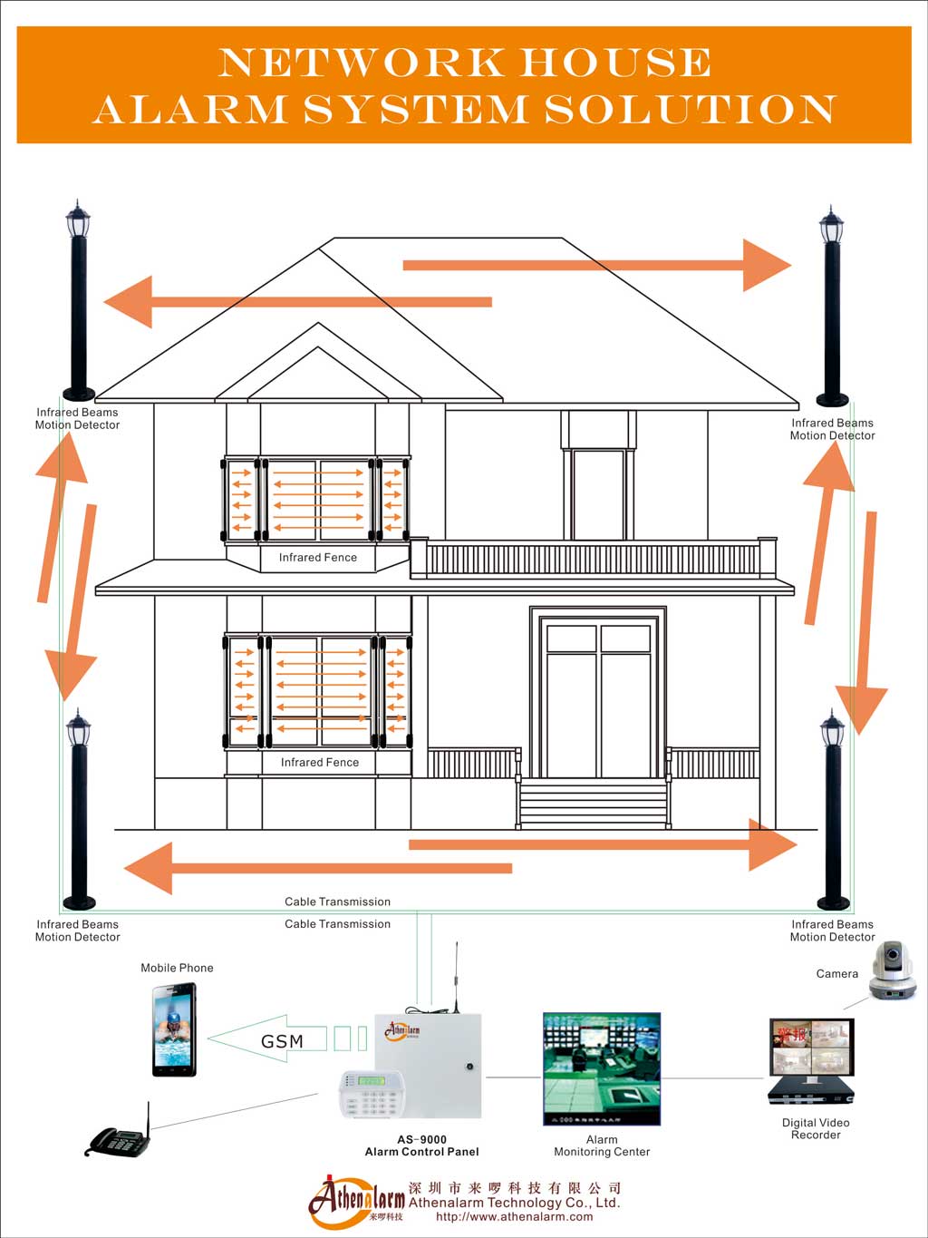
1. Why Security System Selection Is an Architectural Decision
1.1 The Risk Threshold That Determines System Class
Every building carries a measurable risk profile—a combination of asset valuation, occupancy patterns, threat exposure, and operational continuity requirements. When that profile exceeds a defined threshold, a consumer-grade alert product no longer satisfies the engineering requirements of the deployment environment. The transition from a self-configured IoT hub to a professionally integrated security platform is not a matter of budget preference; it is a structural consequence of operational risk.
Organizations routinely underestimate the indirect costs embedded in security decisions: the operational disruption caused by a missed alert, the insurance claim denied because monitoring records lacked legal-grade documentation, the municipal fine incurred after a third unverified false alarm dispatch. These are not hypothetical outcomes. They are the downstream consequences of treating security system selection as a procurement transaction rather than an architectural engineering decision.
1.2 From Consumer Alarms to Commercial Security Infrastructure
The engineering distinction between a consumer alarm kit and a commercial-grade security platform begins at the control layer. A consumer device processes events through cloud-hosted logic, making local response dependent on internet connectivity. A professional security platform executes detection logic within an on-premises embedded Real-Time Operating System (RTOS), ensuring that zone supervision, siren actuation, and event logging continue without interruption regardless of WAN status.
This architectural separation—edge-controlled execution versus cloud-dependent processing—produces fundamentally different operational outcomes during power grid events, ISP outages, and deliberate RF jamming attempts. Systems that appear functionally identical during normal operations diverge dramatically under adverse conditions, which are precisely the conditions that security architecture must survive.
1.3 Defining the Real Decision: DIY Convenience vs. Engineered Risk Reduction
The actual procurement question is not “Which system costs less?” It is: at what combination of asset value, compliance obligation, and operational continuity requirement does a property demand a certified, supervised physical security ecosystem over an uncertified consumer IoT solution?
Answering that question requires understanding the architecture of both options, the engineering constraints governing real-world deployments, and the lifecycle consequences of each infrastructure choice. The following analysis follows that progression—from system fundamentals through deployment realities to a structured decision framework—mirroring the specification workflow used by commercial security consultants during project planning.
2. Understanding Modern Security System Architecture
2.1 Core Components of a Professional Security Platform
A professional security system is an engineered physical security platform composed of supervised field devices, a local control panel, a multi-path communication infrastructure, and a certified monitoring backend. Each component occupies a defined position within the signal chain and carries specific engineering constraints that govern its installation and operational behavior.
| Component | Primary Function | Engineering Constraint |
|---|---|---|
| Control Panel | Local event processing via embedded RTOS | Current-draw budget typically 1A–2A on auxiliary rail |
| PIR / Dual-Tech Sensors | Volumetric intrusion detection | Field-of-view calibration required; thermal proximity sensitivity |
| Door / Window Contacts | Perimeter breach detection | Governed by End-of-Line Resistor (EOLR) supervision networks |
| Zone Expanders | Extend addressable zone capacity | Connected via RS-485 multidrop bus; distance-limited to ~1,200 meters |
| Dual-Path Communicator | Event delivery via Ethernet primary + LTE backup | Requires static IP/DNS endpoints at CMS receiver; AES-128/256 encryption |
| Keypads | User interface and arming control | Communicate over supervised RS-485 field bus |
| Central Monitoring Station (CMS) | Event receipt, verification, dispatch | Requires correct account mapping; UL/FM certification defines operational standards |
| Backup Battery | Sustain operation during AC mains failure | Sealed Lead-Acid or LiFePO4; requires periodic dynamic load testing |
These components do not operate as independent devices. They form a supervised signal chain where the failure or misconfiguration of any node affects the integrity of the entire detection path.
2.2 How Alarm Events Travel Through the System
Event propagation in a commercial security platform follows a deterministic path from the physical edge to emergency dispatch. Understanding this flow clarifies why professional architectures produce measurably different outcomes from consumer alternatives.
A physical sensor—a passive infrared (PIR) detector, door contact, or glass break device—monitors its supervised zone loop continuously. When the sensor transitions from normal to alarm state, the control panel’s embedded RTOS processes the zone condition change within milliseconds. The control panel then transmits an encrypted event report to the Central Monitoring Station using the SIA DC-09 protocol over the primary IP channel, with automatic failover to LTE-M cellular if the Ethernet path is unavailable.
Physical Sensor (PIR / Contact)
         │ Supervised EOLR Zone Loop
         ▼
Control Panel (Embedded RTOS)
         │ Encrypted SIA DC-09 over IP / LTE-M
         ▼
CMS Receiver Line-Card
         │ Receiver Integration Protocol
         ▼
CMS Automation Software Engine
         │ Dispatch Workflow
         ▼
Dispatcher Operator Console
         │ CAD Link / Priority Voice Line
         ▼
Public Safety Answering Point (PSAP / 911)
The target propagation latency from edge sensor to CMS receiver is under 10 seconds under normal operating conditions. Local siren actuation occurs on a millisecond timescale, governed entirely by the edge panel’s RTOS without cloud dependency.
2.3 Edge-Controlled vs. Cloud-Dependent Security Architectures
Commercial security deployments utilize an edge-controlled, cloud-supervised hybrid architecture. The distinction matters operationally because it determines which functions survive infrastructure failures.
The edge layer consists of the edge-controlled network intrusion alarm panel running an embedded RTOS. All zone logic, siren control, local event logging, and communicator management execute on this layer. If WAN connectivity fails, the panel continues supervising field devices, triggering sirens, and logging events locally. The cloud layer handles remote programming, interactive mobile applications, configuration management via tools such as DLS/Uplink, and high-level third-party integrations. These functions become unavailable during WAN outages, but they are not life-safety functions.
┌──────────────────────────────────────────────┐
│                 Cloud Layer                  │
│    Interactive Apps  •  Remote Programming   │
└─────────────────────┬────────────────────────┘
                      │ HTTPS / WebSockets
                      ▼
┌──────────────────────────────────────────────┐
│                  Edge Layer                  │
│  Control Panel (RTOS)  •  Dual-Path Comm.    │
└──────┬───────────────────────────────┬───────┘
       │ Supervised RS-485 Bus         │ Proprietary RF (FHSS)
       ▼                               ▼
┌────────────────────┐       ┌────────────────────┐
│  Hardwired Devices │       │  Wireless Devices  │
│  Keypads • Expanders│      │  PIRs • Contacts   │
└────────────────────┘       └────────────────────┘
A purely cloud-dependent architecture—characteristic of most DIY consumer platforms—inverts these priorities. Detection logic resides in cloud servers, app notifications replace dispatch workflows, and local survivability depends entirely on internet availability. When ISP service fails, the monitoring function fails with it.
3. Professional vs. DIY Security Systems: Five Critical Engineering Differences
3.1 Installation Accuracy and Site Engineering
Professional installation begins before a single device is mounted. A site survey establishes the physical threat profile of the property: structural floor plans, primary entry vectors, RF noise floor measurements, and environmental factors that will influence sensor performance over time.
RF spectrum sweeps identify baseline interference sources—microwave ovens, industrial machinery, neighboring wireless networks—that would degrade sub-GHz wireless sensor performance if unaddressed. Passive infrared sensor coverage volumes are calculated against room geometry and thermal source proximity, because mounting a PIR sensor adjacent to an HVAC diffuser or in direct solar path produces persistent false alarms regardless of sensitivity settings. These are measurable engineering variables, not installation preferences.
DIY installations typically bypass this analysis. Peel-and-stick sensors are positioned for convenience rather than coverage geometry. The result is not simply aesthetic—it directly affects detection probability. A sensor mounted two meters from an optimal position can leave a measurable blind spot along a primary entry path. More critically, the absence of loop supervision validation means that a misplaced sensor may appear operational during normal conditions while failing under the tamper scenarios it was installed to detect.
The EMI consideration is particularly consequential for wired installations. Low-voltage communication lines routed parallel to high-voltage AC mains induce electromagnetic interference that manifests as intermittent zone faults on the RS-485 field bus. These faults appear sporadically, making diagnosis difficult, and they often surface only after the system has been commissioned and handed to the end user.
3.2 System Design, Scalability, and Expansion Architecture
Professional systems are designed as infrastructure rather than device collections. Zone planning accounts for future expansion: additional detection zones, remote keypads, integration with access control readers, and the electrical characteristics that expansion changes introduce into the existing field bus.
Expansion via RS-485 zone expanders adds addressable inputs without replacing the control panel, but it also increases the total current load on the auxiliary power rail. Standard commercial panel motherboards carry a regulated current-draw budget typically between 1A and 2A. Adding expanders, sirens, and remote keypads beyond this budget without installing supervised auxiliary power supplies produces voltage instability across all connected devices.
Wireless expansion using PowerG or equivalent proprietary Frequency Hopping Spread Spectrum (FHSS) protocols extends coverage into areas where cable routing is structurally prohibitive. PowerG operates on sub-GHz bands—433 MHz, 868 MHz, or 915 MHz depending on regional regulatory allocation—specifically to avoid the saturation present in the 2.4 GHz spectrum occupied by Wi-Fi, Bluetooth, and consumer IoT devices. This frequency selection is an engineering decision, not a marketing differentiator; sub-GHz propagation achieves greater wall penetration and resistance to deliberate jamming than 2.4 GHz alternatives.
DIY platforms offer modular expansion, but without zone planning or bus architecture validation. Users select components based on perceived coverage need rather than engineered detection geometry, which frequently results in redundant coverage in low-risk zones and measurable gaps in high-risk perimeter areas.
3.3 Reliability Under Real Operating Conditions
Reliability in a commercial security platform is not a function of network uptime. It is a function of architectural resilience—the system’s ability to maintain detection, logging, and communication across simultaneous failure scenarios.
The dual-path communicator architecture addresses communication reliability directly. Under UL2010 compliance requirements, heartbeat polling intervals reach as low as 90 seconds, meaning the CMS receiver will detect a communicator that has gone offline within 90 seconds of the last successful poll. Primary communication uses IP/Ethernet; upon failure, the communicator automatically switches to LTE-M cellular backup without operator intervention. The two paths operate on independent network infrastructure, preventing a single ISP failure from silencing the monitoring channel.
During a simultaneous AC mains and ISP failure—a scenario that occurs during severe weather events and targeted infrastructure attacks—the edge panel sustains operation from battery backup (Sealed Lead-Acid or LiFePO4) while the cellular path maintains event delivery to the CMS. The local RTOS continues executing zone logic and logging events with accurate timestamps regardless of external connectivity.
Consumer DIY platforms typically rely on a single Wi-Fi connection for both device communication and alarm notification. An ISP outage silences the monitoring channel. A battery-draining power outage disables the hub. The two failure modes most likely to accompany an actual intrusion event are precisely the conditions under which self-monitored systems fail first.
3.4 Long-Term Cost vs. Total Cost of Ownership
Purchase price comparison between DIY and professional systems produces a structurally incomplete financial analysis. The relevant metric is Total Cost of Ownership (TCO) across the operational lifecycle: initial capital expenditure, ongoing maintenance labor, false alarm costs, insurance implications, and the financial exposure created by system failures.
| Cost Dimension | Professional System | DIY System |
|---|---|---|
| Initial CapEx | Higher (site survey, professional labor, certified hardware) | Lower (kit pricing, self-installation) |
| Monitoring OpEx | Monthly SLA-based monitoring contract | Optional; often self-managed or low-cost third party |
| False Alarm Costs | Reduced by dual-tech sensors, two-way verification | Higher risk; municipal fines and dispatch suspensions |
| Truck Rolls | Scheduled preventive maintenance; emergency response within 4–24 hours per SLA | User-managed; no SLA obligation |
| Insurance Impact | Premium discounts for certified monitored systems | Limited discount availability; potential claim denials |
| Firmware / Upgrades | Managed by integrator; staged deployment | User-managed; compatibility risk |
| Lifecycle Risk | Lower; professional validation at each maintenance cycle | Higher; degradation often undetected until failure |
The hidden financial exposure of DIY systems concentrates in two areas. First, insurance carriers frequently decline claims when monitoring records cannot satisfy forensic documentation requirements. Second, false alarm fines accumulate rapidly in municipalities that apply progressive penalty structures, with some jurisdictions suspending police dispatch entirely after repeated unverified activations. Neither cost appears in a product comparison but both represent significant operational liability.
3.5 Monitoring, Incident Response, and Operational Resilience
Professional monitoring is not a notification forwarding service. It is a structured operational workflow executed by trained operators within a UL/FM-certified Central Monitoring Station running redundant communication infrastructure.
When an alarm event arrives at the CMS receiver via encrypted SIA DC-09 framing, the enterprise network alarm center management software engine routes it to the dispatcher operator console with account context, event history, and predefined response instructions. The dispatcher executes a verification workflow—which may include two-way audio contact with the premises, video verification via ONVIF-integrated camera feeds, or call-down procedures to designated contacts—before initiating emergency dispatch through Computer-Aided Dispatch (CAD) links to the Public Safety Answering Point (PSAP).
This verification layer serves two engineering functions. It reduces false alarm dispatches, protecting the property from municipal fines and preserving dispatch priority. It also generates a time-synchronized event ledger that constitutes legally admissible documentation for insurance claims, forensic investigations, and regulatory audits.
Self-monitoring via mobile application notification carries none of these operational characteristics. A missed push notification—due to a dead phone battery, app malfunction, or a user in a meeting—produces the same outcome as no monitoring at all. There is no backup operator, no verification protocol, and no documented response timeline.
4. Engineering Trade-Offs That Most Buyers Never Consider
4.1 Hardwired vs. Wireless Infrastructure
The choice between hardwired and wireless sensor infrastructure is not a reliability ranking; it is an engineering optimization against deployment constraints and lifecycle requirements.
Hardwired infrastructure using shielded low-voltage copper cable—typically 18/2, 22/4, or 22/6 AWG depending on device type and run length—provides absolute signal path reliability. Supervised EOLR loops detect opens, shorts, and tamper conditions on the wiring itself, not just at the sensor. There is no battery lifecycle management requirement across the field device population, and the system carries zero susceptibility to RF jamming or spectrum congestion. The operational trade-off is significant upfront labor: cable pulls require structural penetrations, conduit installation, and careful routing discipline to avoid the EMI effects described earlier.
Wireless infrastructure using PowerG FHSS protocols reduces installation disruption dramatically and allows sensor repositioning without recabling. This flexibility is operationally valuable in retrofit environments where existing structure limits cable routing. The trade-off is ongoing: battery replacement intervals must be tracked across every wireless device in the installation, RF signal margins must be validated periodically as the physical environment changes, and the system requires continuous RF spectrum monitoring to detect signal degradation or deliberate jamming attempts. Initial RF coverage validation frequently changes after furniture, shelving, or production equipment is introduced post-installation.
Hybrid deployments—hardwired perimeter contacts with wireless interior volumetric sensors—distribute these trade-offs strategically, applying the higher-reliability technology at the highest-criticality detection points.
4.2 Local Edge Processing vs. Cloud Dependence
The architectural distinction between edge-controlled and cloud-dependent execution carries direct consequences for system behavior during the infrastructure failures most likely to accompany a real security event.
An autonomous edge architecture guarantees local alarm processing, zone supervision, and siren actuation regardless of internet or cloud availability. The embedded RTOS executes detection logic at millisecond timescales, independent of WAN latency or cloud server load. The operational limitation is that remote diagnostic access, firmware mass deployment, and high-level third-party integrations require cloud connectivity to function. Multi-site firmware updates become logistically complex without a cloud management layer.
A cloud-dependent architecture delivers rich remote management capabilities: real-time mobile dashboards, streamlined multi-site provisioning, and seamless third-party automation integrations. The risk is architectural: any life-safety function that depends on cloud-mediated logic becomes vulnerable to WAN outages, cloud infrastructure failures, and service deprecation events. For commercial and life-safety deployments, this dependency represents an unacceptable single point of failure in the detection chain.
4.3 Detection Sensitivity vs. False Alarm Rate
Detection sensitivity and false alarm rate occupy opposite ends of the same engineering trade-off. Tuning a PIR sensor to detect micro-movements and fast thermal transitions improves detection probability against sophisticated intruders but increases susceptibility to environmental false triggers: HVAC airflow cycling, solar radiation shifting across reflective surfaces, and thermal gradients generated by industrial equipment.
The operational consequence of high false alarm rates is measurable and cumulative. Municipal authorities apply progressive fine structures to repeat false alarm addresses. Police departments suspend priority dispatch after a threshold number of unverified activations. End users develop alarm fatigue and begin bypassing zones or delaying response investigation—precisely the behavioral pattern that sophisticated intruders exploit.
Dual-Technology (PIR + Microwave) detection addresses this trade-off by requiring simultaneous confirmation from two independent detection modalities before generating an alarm event. Passive infrared detects thermal movement; microwave Doppler radar confirms physical displacement. Both technologies must trigger within the same detection window. This configuration virtually eliminates environmentally induced false alarms while maintaining detection probability against actual intrusions—at the cost of slightly higher procurement expense and the requirement for accurate calibration of both detection modalities during commissioning.
4.4 Consumer Simplicity vs. Commercial Compliance
DIY security platforms optimize for installation simplicity: guided setup flows, pre-paired devices, and consumer-accessible configuration interfaces. This simplicity carries a structural compliance cost that is invisible during setup but surfaces during insurance audits, incident investigations, and regulatory inspections.
Commercial compliance requirements—including UL2010 heartbeat monitoring intervals, NFPA life-safety integration standards, and insurance carrier documentation requirements—specify architectural characteristics that consumer products are not designed to satisfy. UL2010 compliance mandates dual-path heartbeat polling at intervals down to 90 seconds. NFPA standards govern the integration of fire, gas, and life-safety sensor types into the alarm platform. Insurance carriers increasingly require documented monitoring records with cryptographic time-stamping to approve high-value claims.
A consumer DIY platform that lacks EOLR-supervised wiring, dual-path communication redundancy, and certified monitoring documentation does not satisfy these requirements regardless of its feature set. The compliance gap is not a matter of configuration—it reflects fundamental architectural differences in how the two system classes are designed.
5. Deployment Realities That Separate Professional Systems from DIY Installations
5.1 Site Surveys and Threat Modeling
Commercial security deployment begins with a structured threat assessment before any hardware is specified. The site survey evaluates building construction materials, entry point exposure, occupancy patterns, and environmental conditions that will affect sensor performance throughout the system lifecycle.
Structural RF barriers—foil-backed insulation, reinforced concrete, low-E coated glass, and metal shelving—require specific attention during wireless coverage planning because their attenuation characteristics are not visible from architectural drawings alone. A building that appears straightforward on a floor plan may present significant RF propagation challenges once actual construction materials are measured in the field. RF spectrum sweeps establish the baseline noise floor at the installation site, identifying interference sources that would degrade wireless signal margins before any devices are installed.
PIR coverage volume calculations account for mounting height, detection angle, and proximity to thermal sources. A sensor mounted above an HVAC diffuser will generate persistent false alarms regardless of its sensitivity adjustment, because the thermal gradient produced by cyclic airflow mimics the infrared signature of human movement within the PIR’s detection frequency band. Identifying and avoiding these mounting conflicts during the site survey phase prevents nuisance alarm patterns that would otherwise require post-installation correction and truck rolls.
Design gaps identified during threat modeling carry direct liability implications. If an undetected breach occurs in a zone that the site survey failed to protect, the installer faces potential errors and omissions (E&O) liability claims. Professional survey methodology—documented with written assessments, RF measurements, and coverage diagrams—creates the evidentiary record that validates design decisions.
5.2 Cabling, RF Coverage, and Environmental Constraints
Physical installation introduces engineering friction that no product specification sheet can fully anticipate. Cable routing decisions made during this phase have long-term operational consequences that surface months or years after commissioning.
Voltage drop along extended RS-485 bus runs is the most common source of intermittent field device failures in commercial installations. Copper wire carries inherent internal resistance: approximately 53 mΩ per meter for 22 AWG conductor. On long bus runs to remote zone expanders or power-hungry siren circuits, this resistance causes the delivered operating voltage to fall below the minimum threshold—typically below 10.5VDC on a 12VDC nominal rail. Devices operating below their minimum voltage threshold exhibit unstable behavior: intermittent communication failures, spurious tamper alerts, and in severe cases, complete device dropout. These symptoms appear sporadically and often correlate with high-current events such as siren activation, making root cause diagnosis non-obvious.
The corrective approach depends on run length and current draw. Upgrading to 18 AWG conductor reduces resistance per unit length by approximately 58% compared to 22 AWG. For very long runs or high-current loads, installing supervised auxiliary power supplies at intermediate points in the field bus provides locally regulated power without extending the voltage-drop path back to the control panel.
End-of-Line Resistor (EOLR) placement determines whether the loop supervision function operates as designed. The resistor must be installed at the absolute physical termination point of the zone loop—inside the sensor housing, as close to the sensor switch contacts as physically possible. For instance, when configuring perimeter-secure door contacts, this loop configuration prevents attackers from executing a low-resistance line bypass between the panel and the entry point. Installing the EOLR inside the panel enclosure defeats loop supervision entirely: an intruder who cuts the field wiring between the panel and sensor creates an open circuit that is physically indistinguishable from a genuine alarm, but a short circuit applied to the wiring—the more practical bypass method—produces a normal-loop resistance value that the panel interprets as a healthy zone.
[Control Panel] ═══════════════ (Long Cable Run) ════════════> [Sensor Switch] ─── [Resistor]
                                                                       ▲               │
                                                                       └───────────────┘
                                                          Correct EOLR placement: Sensor housing
EMI from AC mains induces noise on low-voltage communication lines when the two cable types share conduit or run parallel without adequate separation. The resulting interference manifests as data corruption on the RS-485 bus, producing intermittent zone faults that are extremely difficult to diagnose without a bus analyzer. Maintaining physical separation between high-voltage and low-voltage cable runs—a routing discipline that must be enforced during the cable pull phase, not corrected afterward—prevents this failure mode before it occurs.
5.3 Commissioning and System Validation
Commissioning bridges the gap between hardware installation and operational deployment. Its purpose is not simply confirming that devices power up; it is validating that the complete signal chain from physical sensor to emergency dispatch functions correctly under realistic operating conditions.
Component walk-testing exercises every protected zone sequentially, confirming that each sensor generates the correct zone event at the control panel, that the event record reflects accurate zone identification and timestamp, and that the communicator delivers the event to the CMS receiver with the correct account number and event code mapping. Account configuration errors at the CMS receiver level can cause alarm events to route to incorrect accounts, fall into unmapped event code buckets, or fail to generate automated dispatch flags—all while the control panel registers the event as successfully transmitted.
Failover path validation tests whether the dual-path communicator executes the expected channel switch when the primary Ethernet path is disconnected. Heartbeat polling confirmation verifies that the CMS receiver registers a supervisory event at the correct polling interval. Partition and user permission validation ensures that arming/disarming workflows function correctly under normal occupancy conditions before the system is handed over to the end user.
Firmware versioning must be documented at commissioning and tracked throughout the system lifecycle. Compatibility constraints between older hardware panels and newer cloud communication modules are a persistent operational challenge: firmware updates to the communication module may introduce behavioral changes in the panel’s event reporting logic, and incompatibilities discovered post-commissioning require staged rollback procedures that are operationally disruptive on active life-safety systems.
5.4 Maintenance Throughout the System Lifecycle
Long-term operational reliability in commercial security installations depends on scheduled preventive maintenance rather than reactive repair. Systems that appear fully functional during normal operations often carry degraded components that only reveal their failure state during the adverse conditions—utility outages, high-current siren events, extended WAN failures—that coincide with real security incidents.
| Maintenance Activity | Frequency | Engineering Purpose | SLA Impact |
|---|---|---|---|
| Component Walk-Testing | Annual / Semi-Annual | Verify detection chain integrity | Required for certified compliance and insurance discounts |
| Battery Dynamic Load Testing | Every 6 Months | Confirm standby capacity under actual current draw | Prevents system collapse during grid outages |
| Loop Resistance Telemetry Audit | Quarterly (Remote) | Detect wire corrosion and splice degradation | Identifies faults before they trigger system-wide failures |
| RF Signal Noise Tracking | Continuous (Automated) | Monitor wireless signal margins; detect jamming | Catches deliberate RF interference and environmental degradation |
| Firmware Management | Bi-Annual (Staged) | Apply security patches; maintain compatibility | Mitigates cybersecurity exposure without disrupting life-safety operations |
Battery degradation is operationally invisible during AC-powered operation. A battery that passes a visual inspection and shows normal standby voltage may fail a dynamic load test—the only procedure that applies realistic current draw while measuring voltage under load. Batteries that fail load testing are not simply degraded; they represent a system that will drop out under the first real power outage. Scheduling load tests at six-month intervals establishes a reliable replacement cadence before failure occurs.
Loop resistance telemetry audits detect gradual corrosion at field wiring terminations and sensor housing connections. Corrosion increases the resistance of the EOLR circuit progressively over time, eventually pushing the measured loop resistance outside the panel’s supervised threshold window and generating a zone fault. Identifying this drift quarterly through remote diagnostics allows targeted field visits rather than emergency truck rolls during system failures.
6. Which Security System Fits Your Risk Profile?
6.1 Residential Apartment
A residential apartment presents a low-to-moderate risk profile: limited physical perimeter, single-user occupancy, and no compliance-sensitive assets. A well-configured consumer-grade GSM/Wi-Fi smart alarm system with a supervised contact sensor on the entry door, a PIR covering the primary interior zone, and an optional cellular backup communicator provides adequate coverage when the property has no elevated threat indicators.
The operational limitation appears when connectivity fails. Without backup communication, the monitoring function ceases. For renters with short tenancy horizons and modest asset values, this trade-off may be acceptable. For apartments housing high-value property or residents with personal security concerns, the absence of two-way audio verification and professional dispatch coordination represents a meaningful coverage gap.
6.2 Detached Home
A detached residential property introduces a broader perimeter, multiple entry vectors, and greater asset exposure. A professional system becomes advisable when the property value or occupancy pattern justifies insurance-certified monitoring. The site survey identifies exterior sensor placement requirements, determines whether the RF environment supports wireless deployment, and validates that the chosen communication path survives localized outages.
Insurance carriers offering premium discounts for certified monitored systems typically require documented installation compliance and ongoing professional monitoring contracts—requirements that DIY self-monitoring does not satisfy.
6.3 Retail Store
Retail environments carry elevated daytime foot traffic, cash handling exposure, and after-hours burglary risk. Implementing a dedicated integrated network retail store alarm system solution mitigates these localized vulnerabilities by enforcing strict partition schedules and multi-stage verification pathways. A professional system with video verification capability—integrating ONVIF-compliant cameras with the alarm platform—allows the CMS operator to confirm alarm events visually before dispatching, reducing false alarm costs while maintaining rapid emergency response.
Zone configuration requires careful partitioning: public sales areas carry different arming schedules and user permission levels than stockrooms and cash management areas. RS-485 zone expanders accommodate this complexity without replacing the base panel as the deployment grows.
6.4 Warehouse
Warehouse deployments combine large physical volumes, significant thermal variation from loading dock operations, and extended after-hours vulnerability windows. These environmental characteristics make standard PIR-only detection unreliable: thermal fluctuations from overhead doors, forklifts, and temperature differential between day and night operations generate false alarm signatures that single-technology sensors cannot distinguish from intrusion events.
Dual-Technology (PIR + Microwave) sensors reduce the false alarm rate in thermally dynamic environments by requiring simultaneous confirmation from both detection modalities. Long-range wireless coverage using PowerG FHSS supplements hardwired perimeter contacts at loading dock bays where cable routing through dock levelers and overhead door mechanisms is structurally impractical. This infrastructure integrates seamlessly into a comprehensive industrial network perimeter alarm system solution, ensuring multi-layered edge protection across extensive facility boundaries.
6.5 Office Building
Multi-tenant corporate office environments present complex access scheduling requirements, high insider threat potential, and stringent audit trail demands. Integration with Access Control Systems (ACS) via Open Supervised Device Protocol (OSDP) enables automated disarm sequences when valid credentials are presented at monitored entry points, eliminating the false alarm window associated with manual arming transitions.
Partition architecture segregates tenant zones, allowing individual arming schedules and user permission levels without cross-tenant visibility. Event logs provide the documented audit trail required by corporate governance frameworks and, where applicable, industry-specific regulatory requirements.
6.6 Multi-Site Enterprise
Multi-site enterprise deployments require centralized management platforms that can administer device inventories, user permissions, arming schedules, and firmware versions across geographically distributed installations from a single administrative interface. Deploying an enterprise alarm monitoring system architecture provides central security teams with real-time estate visibility, granular user role assignment, and immutable audit trails across all nodes. Each site maintains a locally autonomous edge panel with independent battery backup and dual-path communication, ensuring that a failure at any individual site does not cascade across the managed estate.
Firmware deployment discipline becomes critical at this scale: compatibility validation must precede any update campaign, and staged rollout protocols allow recovery if an update introduces unexpected behavior on a subset of deployed hardware.
| Scenario | Risk Level | Recommended Architecture | Key Engineering Requirement |
|---|---|---|---|
| Residential Apartment | Low–Moderate | DIY with cellular backup | Single-path acceptable; basic perimeter coverage |
| Detached Home | Moderate | Professional; certified monitoring | Insurance compliance; site survey |
| Retail Store | Moderate–High | Professional; video verification | Zone partitioning; ONVIF integration |
| Warehouse | High | Hybrid; dual-tech sensors | PIR + Microwave; long-range wireless |
| Office Building | High | Professional; ACS integration | OSDP; partition architecture; audit trail |
| Multi-Site Enterprise | Very High | Enterprise managed platform | Centralized management; site autonomy; staged firmware |
7. Professional vs. DIY Security System Comparison Matrix
The following matrix synthesizes the engineering, operational, and commercial distinctions across the full evaluation spectrum. Each dimension reflects architectural behavior rather than feature marketing.
| Evaluation Dimension | Professional Security System | DIY Security System |
|---|---|---|
| Control Architecture | Edge-controlled embedded RTOS; local survivability guaranteed | Cloud-dependent; event processing requires internet connectivity |
| Installation Methodology | Site survey, RF analysis, threat modeling, professional calibration | User-guided app setup; no engineering validation |
| Field Bus Protocol | Supervised RS-485 multidrop; addressable zone expanders | Wi-Fi or Zigbee; no supervised field bus |
| Wireless Protocol | PowerG FHSS on sub-GHz (433/868/915 MHz); RF jamming resistant | 2.4 GHz Wi-Fi or Bluetooth; susceptible to spectrum congestion |
| Alarm Reporting Protocol | SIA DC-09 with AES-128/256 encryption over IP + LTE-M cellular | Proprietary app push notification; no standardized protocol |
| Communication Redundancy | Dual-path: Ethernet primary + LTE backup; 90-second heartbeat polling | Single-path Wi-Fi; no backup channel |
| Monitoring Infrastructure | UL/FM-certified CMS; two-way verification; CAD-linked dispatch | Self-monitoring via mobile app; no professional backup |
| Loop Supervision | EOLR at sensor terminal; detects open, short, and tamper conditions | No wired loop supervision; tampering not detected |
| Scalability | RS-485 expanders, addressable loops, multi-site enterprise management | Device-limited; no structured expansion architecture |
| Integration Capability | OSDP (access control), ONVIF (video), BACnet (BMS), smart home gateways | Limited third-party compatibility; firmware mismatch risk |
| Compliance | UL2010, NFPA, insurance-compliant event documentation | Not designed for regulatory compliance |
| False Alarm Management | Dual-tech sensors, two-way verification, dispatch confirmation | No verification layer; self-managed response |
| Maintenance Model | Scheduled preventive maintenance; SLA-governed response times | User-managed; no SLA obligation |
| Event Documentation | Cryptographically time-stamped immutable audit trail | Limited or no legal-grade event logging |
| Lifecycle Cost (TCO) | Higher CapEx; lower long-term risk exposure and incident costs | Lower CapEx; higher hidden operational and liability costs |
| Disaster Recovery | Hardware watchdog; local logging continues during full WAN failure | Monitoring ceases during WAN or power failure |
8. Key Takeaways
The engineering analysis across the preceding sections converges on several architecture-level conclusions relevant to commercial procurement decisions.
Edge-controlled architecture is a non-negotiable requirement for life-safety deployments. Systems that delegate detection logic to cloud infrastructure introduce a single point of failure at the network boundary—precisely where failures concentrate during the adverse events that security systems must survive.
Loop supervision through correctly placed End-of-Line Resistors is not an installation detail; it is the mechanism that makes the detection path tamper-evident. EOLR placement at the panel enclosure rather than the sensor terminal defeats this function entirely, creating a monitored system that cannot detect its own bypass.
Total Cost of Ownership analysis consistently favors professional systems when asset value, compliance requirements, or operational continuity demands are elevated. False alarm fines, insurance claim denials, emergency truck rolls, and undocumented incident responses represent financial exposure that does not appear in a hardware price comparison.
The threshold that determines appropriate system class is defined by operational risk, not budget. A small residential property with limited asset exposure and no compliance obligations may be well-served by a correctly configured DIY system. A multi-tenant commercial facility, a warehouse with after-hours vulnerability, or any environment with insurance-governed documentation requirements demands a certified, professionally supervised security architecture. Deploying below that threshold creates technical debt that surfaces during the events the system was installed to prevent.
9. FAQ
9.1 System Fundamentals
Q: What is the difference between a security system and an alarm system?
An alarm system is a specific component category—devices that generate audible or visual alerts upon event detection. A security system is the complete engineered platform encompassing sensors, control panels, communication infrastructure, monitoring workflows, and event documentation. All alarm systems are components within a broader security system, but a security system provides detection, verification, dispatch, and audit functions that a standalone alarm cannot deliver.
Q: What components are required in a commercial-grade security system?
A commercial-grade platform requires a supervised control panel with embedded RTOS, zoned detection devices (PIR, contacts, dual-tech), End-of-Line Resistor networks on every supervised loop, a dual-path communicator (IP + LTE), a UL/FM-certified Central Monitoring Station connection, battery backup power, and cryptographic event logging. Any architecture missing loop supervision, redundant communication, or certified monitoring does not qualify as commercial-grade regardless of its feature set.
Q: Why are professional security systems more than connected smart devices?
Professional platforms execute detection logic locally through an embedded RTOS, maintain tamper-supervised wiring through EOLR networks, deliver events via encrypted SIA DC-09 protocol, and operate continuously through power and internet failures. Consumer smart devices route logic through cloud servers, lack wiring supervision, use unencrypted proprietary push notifications, and fail when internet connectivity is unavailable.
9.2 Architecture & Technology
Q: What is an edge-controlled security system and why does it matter?
An edge-controlled system hosts all detection logic, zone supervision, siren management, and event logging within the on-premises control panel running an embedded RTOS. This architecture guarantees local operation during WAN outages, ISP failures, and cloud infrastructure events. Life-safety functions are never dependent on external network availability. Cloud services augment the system with remote management and configuration without becoming part of the life-safety execution path.
Q: Why is SIA DC-09 replacing legacy Contact ID alarm reporting?
Contact ID (SIA DC-05) transmits 4-digit alarm codes over DTMF tones on analog PSTN lines. Global PSTN network sunsets are eliminating this infrastructure. SIA DC-09 encapsulates alarm event metadata—including account identifiers, event codes, and partition data—into AES-128/256 encrypted TCP/UDP packets delivered over IP and cellular networks. Most modern deployments use physical IP communicators that intercept legacy DTMF tones from existing panel dialers and re-encapsulate them as SIA DC-09 frames, preserving legacy panel investments without requiring full panel replacement.
Q: How do professional systems continue operating during an internet outage?
The embedded RTOS on the edge panel continues executing zone logic, triggering sirens, and logging events locally without any internet connection. The dual-path communicator automatically switches from primary Ethernet to LTE-M cellular backup within the heartbeat polling window—down to 90 seconds under UL2010 compliance—maintaining event delivery to the CMS. Battery backup sustains both the panel and communicator during simultaneous power and connectivity failures.
Q: Why do professional systems use dual-path communication?
Single-path communication creates an unacceptable dependency on one infrastructure provider. Ethernet and LTE-M operate on independent network infrastructures: a localized ISP outage that takes down the primary Ethernet path does not affect the cellular backup, and a regional cellular event does not affect the IP path. Heartbeat polling at intervals as low as 90 seconds ensures the CMS receiver detects a communicator failure within minutes rather than hours, maintaining supervisory oversight of the entire monitored estate.
9.3 Deployment & Installation
Q: Why is a professional site survey necessary before installation?
A site survey measures the physical variables that determine system performance: structural RF attenuation characteristics, baseline noise floor, thermal source proximity to sensor mounting positions, cable routing constraints, and entry vector analysis. These variables cannot be inferred from floor plans. RF coverage predictions calculated without site measurements frequently fail once furniture, shelving, or equipment are installed post-survey. Sensors placed without thermal source analysis generate persistent false alarms. Design decisions made without documented survey data create E&O liability exposure for the installing contractor.
Q: Why does EOLR placement inside the control panel defeat loop supervision?
When the End-of-Line Resistor is placed inside the panel enclosure, the supervised circuit only extends from the panel to the far end of the field wiring—not through the sensor itself. An intruder who applies a short circuit across the field wiring anywhere between the panel and sensor produces a resistance reading identical to a properly closed sensor loop. The panel cannot distinguish between normal operation and a deliberately shorted wire. Placing the EOLR inside the sensor housing ensures that the complete wire run, sensor contacts, and field terminations are within the supervised circuit.
Q: Why can improper wiring reduce security system reliability?
Two primary mechanisms degrade reliability. First, voltage drop on extended RS-485 bus runs causes remote devices to operate below their minimum voltage threshold—typically below 10.5VDC on a 12VDC nominal rail—producing intermittent communication failures and false tamper alerts. Second, low-voltage communication cables routed parallel to high-voltage AC mains induct electromagnetic interference into the RS-485 bus, generating data corruption that manifests as sporadic zone faults. Both failure modes are intermittent, difficult to diagnose remotely, and prevent the installer from presenting as hardware defects.
Q: What happens during system commissioning?
Commissioning validates the complete detection chain rather than individual device functionality. Each zone is walk-tested sequentially to confirm correct event generation, panel registration, and CMS receipt with accurate account number and event code mapping. Failover communication paths are tested by disabling the primary Ethernet channel and confirming automatic LTE switchover within the heartbeat window. User permissions, arming schedules, and partition configurations are verified before system handover. Account configuration errors at the CMS receiver level—a common omission—can prevent alarm dispatch despite successful signal transmission, and this failure only surfaces during full end-to-end commissioning validation.
9.4 Reliability & Monitoring
Q: What is professional alarm monitoring and how does it differ from self-monitoring?
Professional alarm monitoring is a structured operational service executed by trained operators within a UL/FM-certified Central Monitoring Station. When an alarm event arrives via encrypted SIA DC-09, the operator follows a predefined verification workflow—including two-way audio, video verification, and call-down procedures—before initiating emergency dispatch through CAD-linked channels to the PSAP. Self-monitoring forwards push notifications to the user’s mobile device with no backup operator, no verification protocol, and no documented response timeline. If the notification is missed for any reason, no response occurs.
Q: How does heartbeat supervision improve system reliability?
Heartbeat supervision requires the communicator to transmit a supervisory signal to the CMS receiver at defined intervals. Under UL2010 compliance, these intervals can be as short as 90 seconds. If the receiver does not receive a heartbeat within the expected window, it generates a trouble event and initiates a diagnostic response. This mechanism ensures that a failed communicator—whether due to hardware fault, power loss, or deliberate physical tamper—is detected and acted upon within minutes rather than remaining unnoticed until the next alarm event.
Q: Why are event audit trails important after a security incident?
Cryptographically time-stamped event logs provide the legally admissible documentation that insurance claims, forensic investigations, and regulatory audits require. Records must demonstrate when alarm events occurred, which zones activated, what user interactions preceded the event, and how the monitoring center responded. Systems lacking immutable event logging with accurate timestamps cannot satisfy insurance carrier documentation requirements, potentially resulting in claim denial regardless of the underlying security event.
9.5 Operations & Maintenance
Q: How often should a commercial security system be serviced?
Component walk-testing should occur at minimum annually, with semi-annual intervals recommended for high-occupancy or compliance-sensitive environments. Battery dynamic load testing should be performed every six months. Loop resistance telemetry audits can be conducted quarterly through remote diagnostics. RF signal margin monitoring should be continuous for wireless-heavy installations. Firmware management follows a bi-annual staged cycle coordinated between the integrator and hardware manufacturer to maintain cybersecurity posture without disrupting active life-safety operations.
Q: Why do backup batteries require periodic dynamic load testing?
Standby voltage measurements do not reveal battery capacity degradation. A battery that shows normal open-circuit voltage may fail within minutes of carrying the current load required during an actual power outage. Dynamic load testing applies a current draw approximating real operational conditions while measuring the voltage response under load. Batteries that cannot sustain the minimum operating voltage threshold across the test duration must be replaced. Static voltage checks alone cannot detect this failure mode, making periodic load testing the only reliable capacity validation method.
Q: What causes false alarms in professional security systems?
The most common source is PIR sensor exposure to thermal movement that mimics a human intrusion signature: HVAC airflow cycling near sensor coverage volumes, solar radiation shifting across reflective surfaces within the detection field, and thermal gradients produced by industrial equipment or loading dock operations. The engineering mitigation is Dual-Technology (PIR + Microwave) detection, which requires simultaneous confirmation from both modalities before generating an alarm event. Secondary sources include EOLR mismatch or corrosion causing loop resistance drift into alarm thresholds, and improper sensor placement during installation.
Q: Why is preventive maintenance more effective than reactive repairs?
Reactive repair addresses failure after it has already compromised system integrity—often during or after an actual security event. Preventive maintenance identifies degradation before it crosses the failure threshold: catching battery capacity decline before the first utility outage, identifying loop resistance increase from corrosion before the zone generates a false fault, and validating RF signal margins before environmental changes reduce them below reliable operation levels. Scheduled maintenance also satisfies contractual SLA requirements and maintains the system’s compliance certification status with insurance carriers.
9.6 Compliance & Risk
Q: Why do insurance companies prefer professionally monitored security systems?
Certified monitored systems provide the documented operational record—time-stamped event logs, verified dispatch records, and installation compliance documentation—that insurance carriers require to validate claims and assess risk. Systems holding UL/FM certification demonstrate that the monitoring infrastructure meets independently verified reliability standards. Insurance carriers quantify this risk reduction as a measurable premium discount, typically requiring both professional installation and active monitoring contracts. Self-monitored systems without these documentation capabilities generally cannot satisfy carrier requirements for premium adjustments.
Q: What role do UL and NFPA standards play in commercial security?
UL certification for monitoring stations (e.g., UL2010 for dual-path communication intervals) and for specific equipment categories establishes that the hardware and operational procedures have been independently tested against defined performance benchmarks. NFPA standards govern the integration of life-safety systems—fire detection, gas sensing, emergency evacuation—into the alarm platform, specifying response time requirements, redundancy minimums, and documentation practices. Both frameworks define the engineering floor below which commercial installations create liability exposure for the installing contractor and the property owner.
Q: How does correct End-of-Line Resistor placement improve security?
Correct EOLR placement at the physical sensor terminal creates a fully supervised loop that detects three distinct conditions: normal (sensor closed, resistor in circuit), alarm (sensor open), and tamper (wiring short or open outside the sensor). Panel-side placement only supervises the wire run, leaving the sensor itself unsupervised. An intruder who cuts or shorts the field wiring between a panel-side resistor and the sensor cannot be distinguished from normal operation, effectively creating a bypassable detection path.
9.7 Procurement & Cost
Q: Why is Total Cost of Ownership more meaningful than purchase price?
Purchase price captures only the initial capital expenditure. TCO includes ongoing monitoring costs, preventive maintenance labor, truck roll expenses for reactive repairs, municipal false alarm fines, insurance premium differences, and the financial exposure created by system failures—denied insurance claims, liability from undetected breaches, and the operational cost of downtime. Professional systems carry higher CapEx but reduce incident frequency through engineering discipline, lower OpEx through scheduled maintenance, and reduce financial exposure through compliant documentation. DIY systems invert this structure: low CapEx offsets by higher cumulative operational and liability costs.
Q: When does a DIY security system become a business risk?
A DIY system creates measurable business risk when any of the following conditions apply: the property value or operational continuity requirement exceeds the coverage threshold of self-monitoring; compliance documentation is required by insurance carriers, regulatory bodies, or commercial tenants; the installation environment introduces engineering variables—voltage drop, EMI, RF attenuation—that require professional validation; or the occupancy pattern creates access control requirements that consumer platforms cannot satisfy. These thresholds are not absolute; they depend on a structured risk assessment rather than a fixed asset value.
Q: What types of properties benefit most from professional security systems?
Commercial office buildings, retail environments, warehouses, multi-tenant facilities, and any property subject to insurance compliance requirements or regulatory audit obligations benefit directly from professional architecture. The benefit is proportional to asset value, occupancy complexity, operational continuity requirements, and the compliance documentation burden. Small, low-risk residential properties with straightforward perimeters and no compliance obligations represent the primary appropriate use case for well-configured DIY solutions.
9.8 Expansion & Integration
Q: Can professional security systems be expanded over time?
Professional systems are architected for expansion from initial deployment. Zone expanders connected to the RS-485 field bus add addressable inputs without replacing the control panel. Wireless transceivers integrate supervised sensor networks for areas where cable extension is impractical. Multi-site deployments scale through enterprise head-end software that manages device inventories, user permissions, and firmware versions across geographically distributed installations. Expansion planning must account for the cumulative impact on the auxiliary power rail current budget and field bus addressing capacity.
Q: How do professional systems integrate with access control?
Integration with Access Control Systems uses the Open Supervised Device Protocol (OSDP), a bidirectional encrypted communication standard between the security panel and access control readers. Valid credential presentation at an OSDP reader triggers an automated disarm sequence for the corresponding alarm partition, eliminating the false alarm window that occurs when users must manually disarm before the entry delay expires. OSDP also provides reader tamper supervision and encrypted credential data, improving the overall security posture of the access control integration.
Q: How do security systems integrate with video management platforms?
Professional systems integrate with Video Management Systems (VMS) through ONVIF Profile S or Profile T, the universal standard for IP video interoperability. An alarm event on the security panel sends a hardware relay closure or IP trigger to the VMS, initiating pre-alarm video buffering and making the relevant camera feeds immediately available to the CMS operator for visual verification. This integration requires adequate network bandwidth for RTSP stream management and proper edge switch configuration to prevent saturation during simultaneous alarm and video events.
Q: Can security systems integrate with building management systems?
Integration with Building Management Systems (BMS) occurs via dry contact relays for simple on/off state changes or through BACnet protocol for higher-level data exchange. During a life-safety event—fire alarm, gas detection, or forced entry—the security platform signals the BMS to execute HVAC shutdown sequences, activate stairwell pressurization, or modify elevator recall configurations. These integrations require careful coordination between the security integrator and the BMS contractor to ensure that life-safety event priorities do not conflict with building automation schedules.
9.9 Troubleshooting
Q: Why do long cable runs cause intermittent device failures on an RS-485 bus?
Copper conductor resistance is approximately 53 mΩ/meter for 22 AWG wire. On extended RS-485 runs serving remote expanders or siren circuits, the voltage delivered at the terminal device is reduced by the resistive drop across the full conductor length. When this drop causes the device to receive below 10.5VDC on a 12VDC nominal rail, the device enters an unstable operating region: intermittent communication dropouts, spurious tamper events, and occasionally complete device loss. Symptoms typically appear first during high-current events—siren activation draws maximum current—because additional current through the same resistance produces proportionally greater voltage drop.
Q: Why do motion detectors generate false alarms near HVAC vents?
PIR sensors detect the infrared radiation differential produced by objects moving through their detection field. HVAC diffusers produce cyclic warm and cold airflows that create thermal gradients within the sensor’s coverage volume. When airflow rates or temperature differentials exceed the sensor’s discrimination threshold, the thermal gradient mimics the radiation signature of a moving human body, triggering an alarm event. The engineering resolution is Dual-Technology detection, requiring simultaneous PIR and Doppler microwave confirmation. Microwave radar detects physical displacement rather than thermal radiation, and airflow alone does not produce a Doppler shift that satisfies the microwave threshold, preventing the false alarm.
Q: How should technicians troubleshoot unstable field devices showing intermittent faults?
Start with loop resistance measurement using a calibrated meter at the panel terminal with the device disconnected. Compare the measured resistance against the expected EOLR value and conductor resistance for the known cable run length. Resistance values significantly above the expected range indicate splice corrosion, conductor damage, or an undersized cable gauge for the run length. Next, measure operating voltage at the device terminal under load by connecting the device and activating any connected siren or output circuit. Voltage below 10.5VDC at the device terminal under load confirms voltage drop as the root cause. Upgrade conductor gauge, add an auxiliary power supply at the field bus midpoint, or segment the run to reduce the total resistance path.
10. Appendix
To assist system integrators and security architects in maintaining physical compliance and operational verification across various deployment verticals, the following engineered components and specialized sub-system frameworks are recommended for architectural review:
- Global Security Manufacturing Infrastructure: Professional Burglar Alarm Manufacturer Platform
- Next-Gen Network Signaling: Commercial Burglar Alarm System Infrastructure
- Unified Centralized Back-End Architecture: Network Alarm System Platform
- Advanced Monitoring Delivery Matrix: Network Alarm Monitoring System Solution
- Scaled Network Security Topology: Network Alarm Monitoring System Application
- Financial Institution High-Security Blueprint: Banking Infrastructure Network Security Solution
- Distributed Banking Edge Node Defense: Bank ATM Cryptographic Security Solution
- Ultra-High-Risk Vault Area Supervision: High-Security Bank Vault Monitoring Solution
- Master-Planned Estate Multi-Dwelling Framework: Commercial Community Security Solution
- Engineered Private Estate Architecture: Engineered Residential Security Solution
- Commercial Hospitality Access-Linked Systems: Commercial Hotel Security Solution
- General Information Gateway & Standards Index: Athenalarm Engineering Portal
- Volumetric Interior Intrusion Verification: Volumetric PIR Motion Sensor Components
- High-Density Open Space Volumetric Defense: High-Density Wide-Angle PIR Motion Sensors
- Life-Safety Integrated Fire Detection Nodes: Early-Warning Photoelectric Smoke Detectors
- Hazardous Environmental Condition Mitigation: Industrial-Grade Combustible Gas Detectors
- Structural Penetration and Safe-Vault Perimeter Defense: High-Precision Digital Vibration Detectors
- Hardwired Under-Counter Tactical Duress Anchors: Hardwired Emergency Duress Panic Buttons
- Supervised Mobile Guard-Patrol Duress Arrays: Supervised Wireless Emergency Panic Buttons
- Localized Real-Time Local Incident Annunciation: Edge-Triggered Motion Sensor Voice Alert Broadcast Systems
- High-Decibel Industrial Status Indicators: Industrial Visual Status Warning Light Systems
