

Integrating Security Management: Engineering Unified Physical Security Platforms for Enterprise Resilience
1. From Isolated Systems to Unified Operational Intelligence: The Architectural Imperative
1.1 Why Fragmented Physical Security Architectures Fail at Scale
Every enterprise physical security failure investigated over the past decade shares a structural precondition: the systems involved were not malfunctioning in isolation—they were operating exactly as designed, but in complete ignorance of each other. An intrusion sensor trips at 02:14. The access control system logs an anomalous card swipe on the same corridor at 02:13. The video management system captures a usable frame at 02:15. None of these events automatically cross-reference. The correlation happens hours later, manually, inside a spreadsheet.
This is the operational cost of fragmentation. At the scale of a corporate campus, a critical infrastructure site, or a distributed retail network, siloed architectures do not simply reduce efficiency—they create latency windows that adversaries exploit and that life-safety protocols cannot tolerate. The failure mode is not a component breakdown; it is an architectural one.
The Unified Security Platform (USP)—also deployed under the designations Physical Security Information Management (PSIM) system and Security Management System (SMS)—exists specifically to eliminate this latency window. Its function is not to replace the Intrusion Alarm System (IAS), the Access Control System (ACS), or the Video Management System (VMS). Its function is to act as the orchestration tier above all of them: normalizing their disparate southbound data streams, correlating their asynchronous events, and executing automated cross-system responses without requiring human arbitration at the moment of incident.
1.2 Defining the Operational Scope of Integrated Security Management
Integrating security management, in precise architectural terms, refers to the consolidation of independent physical security and building automation subsystems into a single, unified operational platform that enables real-time data exchange, event correlation, and coordinated automated response. This definition excludes simple alarm aggregation dashboards, which collect alerts without executing correlation logic or automation rules. In contrast, deploying a fully integrated enterprise alarm monitoring system ensures that data normalization occurs at the ingestion tier, allowing for advanced cross-subsystem event coordination.
The boundary of a fully integrated platform begins southward at the communication interfaces of edge control panels—the Intrusion Panel, the Access Control Main Controller, the VMS network switch—and extends northward to client workstation applications, mobile alert delivery systems, and Central Monitoring Station (CMS) receiver interfaces. Between these boundaries, the USP performs four core functions:
- Data Aggregation and Normalization: Translating heterogeneous southbound protocol streams (RS-485, OSDP, SIA DC-09, ONVIF, BACnet/IP) into a unified state-machine data model.
- Event Correlation and Causality Linking: Associating temporally proximate events across different subsystems—matching a Zone 4 Door Forced Alarm from the IAS with a concurrent access card rejection logged by the ACS and a video clip from Camera 12 captured by the VMS.
- Automated Workflow Execution: Triggering cross-system responses via pre-configured Event-to-Action matrices without human intervention during high-stress scenarios.
- Centralized Command and Control: Delivering a unified graphical interface—the single pane of glass—for real-time monitoring, event acknowledgement, and full audit lifecycle management.
1.3 Who This Architecture Is Designed For
The integrated security architecture described in this document is engineered for Enterprise Security Directors responsible for multi-site physical security governance, Master Systems Integrators (MSIs) executing complex cross-vendor deployments, Physical Security Architects designing resilient enterprise environments, and Critical Infrastructure Operators managing airports, seaports, data centers, and utility facilities. Generic alarm monitoring guidance is not the objective here. The target reader requires tactical integration methodology: protocol stack mechanics, deployment phase validation, failure mode diagnostics, and architectural trade-off resolution.
2. Core Architecture of an Integrated Security Platform
2.1 Unified Security Platform Core Engine
The Unified Security Platform Core Engine operates as the central orchestration layer within the integrated architecture. It does not generate raw security data—it consumes, normalizes, correlates, and acts upon data produced by subordinate subsystems. Deployed either on an on-premise high-availability server cluster or a hybrid cloud-connected infrastructure, the USP core engine maintains the master configuration repository, the event correlation rule engine, the Event-to-Action automation matrix, and the unified operator dashboard. This infrastructure underpins the entire network alarm monitoring system solution, serving as the deterministic processing hub for all multi-tenant or multi-site telemetry data.
A critical architectural characteristic is that the USP Core Engine does not own physical security decisions at the edge. Local edge controllers—intrusion panels, access control main controllers, door interface modules—retain autonomous local databases and execute all core security, access, and life-safety logic natively. The USP tier acts as the aggregation, visualization, and automation coordination layer. This separation is deliberate and operationally significant: it preserves edge survivability during WAN connectivity failures.
2.2 Intrusion Alarm System Integration
The Intrusion Alarm System (IAS) feeds the USP through a structured protocol pathway. At the physical layer, magnetic contacts, Passive Infrared (PIR) motion detectors, glass-break sensors, and vibration detectors connect to zone input terminals on the intelligent intrusion alarm control panel via supervised wiring loops. The intrusion panel’s core logic processor translates zone state changes into standardized alarm event packets and transmits them upstream to the USP via the SIA DC-09 protocol over IP.
The integration dependency chain is precise:
Physical Sensor Asset → End-of-Line (EOL) Resistor Network → Intrusion Panel Input Zone Line → SIA DC-09 Integration Driver → Network Switch Security VLAN → USP Core Engine
Each link in this chain carries a specific engineering responsibility. The EOL resistor network provides continuous electrical line supervision, allowing the panel to distinguish between four discrete states: Open Circuit, Short Circuit, Normal Closed State, and Active Alarm State. The SIA DC-09 driver converts low-level zone state transitions into timestamped, encrypted IP packets for network transmission to the USP and ultimately to the CMS receiver.
2.3 Access Control System Integration
The Access Control System (ACS) integrates with the USP primarily through the Open Supervised Device Protocol (OSDP) at the field layer and via REST APIs or proprietary SDK interfaces at the application layer. The Access Control Main Controller manages credential databases, door schedule tables, and lock output relay states locally. The USP communicates event triggers and automated lockdown commands to the ACS main controller, which then translates them into physical relay operations at door hardware.
The automation dependency for a lockdown scenario follows this path:
USP Core Engine Automation Rule → Access Control Main Controller → Lock Output Relay → Electromagnetic Door Lock
This chain must execute with deterministic low latency. Network QoS configurations on the security VLAN are mandatory to guarantee this path is not throttled by competing traffic during high-event-density scenarios.
2.4 Video Management System Integration
The Video Management System (VMS) integrates with the USP via the ONVIF standard, specifically Profiles S (live streaming and PTZ control), G (edge storage query), T (metadata and analytics), and M (media profile management). The critical integration function is alarm-driven video association: when the USP receives a Zone 4 Door Forced Alarm from the IAS, it immediately commands the VMS API client to retrieve the live feed from Camera 12, push the stream to the operator’s Monitor 2, and initiate a tagged recording session with the alarm event ID embedded in the clip metadata.
ONVIF compatibility friction is a recurring operational reality. Minor vendor implementation variances—particularly in analytics event metadata formatting and custom event trigger mapping—frequently cause dropped event packets between camera firmware revisions and VMS software updates. Regression validation after any VMS or camera firmware update is not optional in an integrated environment; it is a commissioning obligation.
2.5 Building Management System Integration
The Building Management System (BMS) integration introduces the highest inter-domain security risk within the platform architecture. The USP forwards occupancy telemetry—derived from PIR motion events and ACS card swipe logs—to HVAC and lighting controllers via BACnet/IP. However, this integration path must be enforced through a unidirectional protocol gateway.
A bidirectional, unprotected bridge between the BACnet/IP BMS network and the security VLAN creates a lateral attack surface: a compromised HVAC controller could potentially reach intrusion panel communication pathways. The engineering resolution is explicit: deploy a hardware protocol gateway that passes occupancy data from the security OT network to the BMS network in one direction only, with no return data path into the security domain.
Life-safety override represents a separate, hardwired integration dependency. The Fire Alarm Control Panel (FACP) must connect to the access control relay infrastructure via hardwired or network-isolated relay inputs that physically override normal security lock states. This fail-safe path must function independently of the USP software layer—if the USP core engine is offline during a fire event, egress doors must still unlock.
2.6 Central Monitoring Station Connectivity
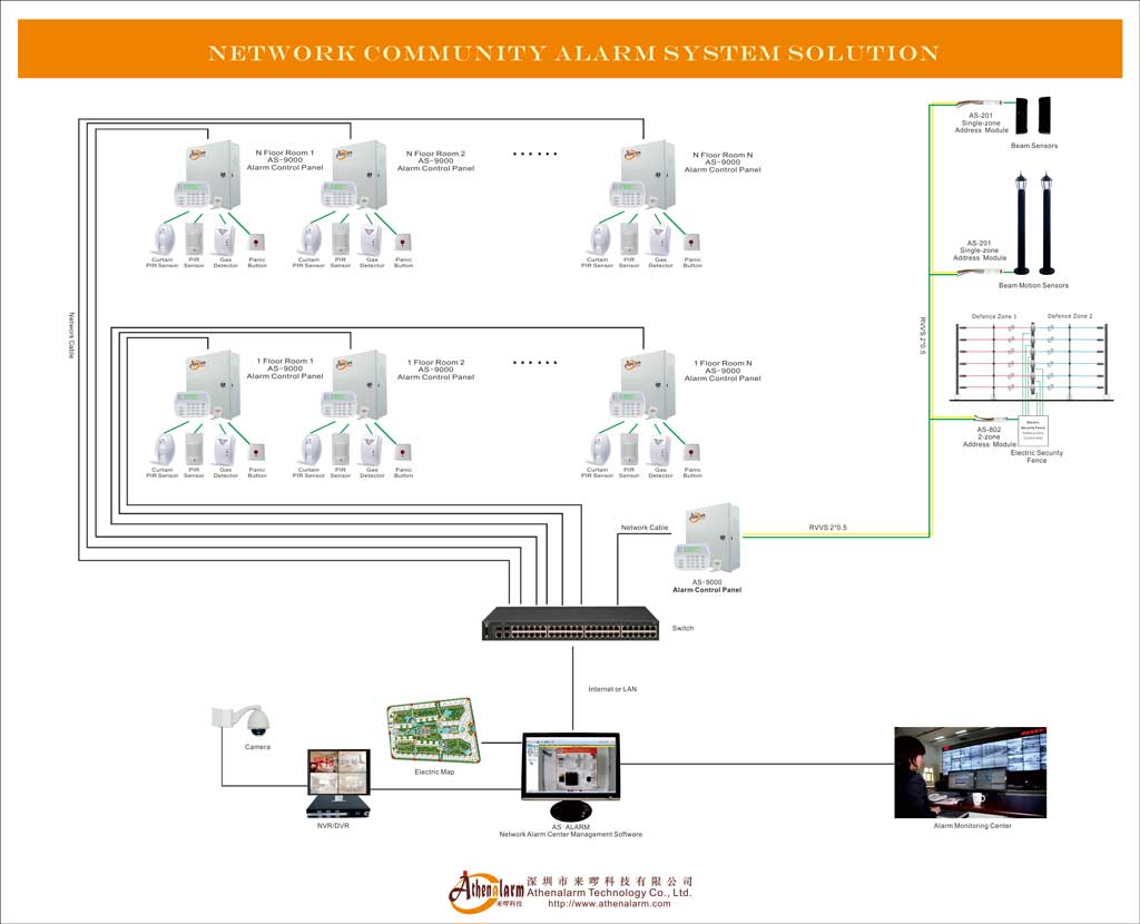
The CMS integration layer defines how automated system data becomes actionable emergency dispatch. The USP maps internal event codes to standardized SIA or Contact ID reporting tokens and transmits validated alarm packets to the CMS receiver hardware gateway via SIA DC-09 over IP. To process these streams effectively, the central monitoring hub relies on industrial-grade network alarm center management software to cross-reference incoming SIA DC-09 tokens against the master facility database. Redundant reporting pathways are mandatory: primary transmission over the main ISP Ethernet link, with automatic failover to an LTE cellular secondary path via a separate carrier.
USP Core Engine → SIA Receiver Hardware Gateway → CMS Automation Database Workstation
Polling interval configuration is a frequent commissioning failure point. Improperly set keep-alive heartbeat intervals cause the CMS to generate frequent “Receiver Supervision Failure” tickets during minor network jitter events, creating alarm fatigue for dispatch personnel and masking genuine connectivity failures.
3. Communication Architecture and Protocol Stack
3.1 Field Layer Communications
The physical communication layer between security control hardware and edge devices operates across two dominant bus technologies: RS-485 serial and the legacy Wiegand interface.
RS-485 functions as the local serial data bus connecting the intrusion control panel to remote keypads, zone expander boards, and relay output modules. The standard physical configuration is a continuous daisy-chain topology, not a star or stub layout. A star topology on RS-485 introduces impedance discontinuities at each branch junction, causing signal reflections that manifest as intermittent module communication faults.
The termination resistor placement rule is absolute: a 120 Ω resistor must be placed at the physical ends of the RS-485 cable run—not inside the panel cabinet, not at the nearest convenient junction box, but at the last physical device on the bus. A missing or misplaced termination resistor on an extended RS-485 run produces signal reflections that corrupt packet bytes, generating device fault reports that appear and disappear without clear cause. Field technicians routinely spend days hunting these faults before the termination error is identified.
OSDP (Open Supervised Device Protocol) operates over the same RS-485 physical layer but replaces the Wiegand logical protocol for card reader-to-panel communication. OSDP introduces AES-128 bidirectional encryption and continuous line supervision—capabilities that Wiegand structurally cannot provide.
Wiegand remains the most widely deployed reader interface in retrofit projects due to its installed base volume, but its security posture is indefensible in modern enterprise environments. Wiegand transmits credential data in an unencrypted, unidirectional signal with no line supervision capability. Physical inline intercept tools such as ESPKey can capture and replay Wiegand credential packets without triggering any system alert. For any deployment handling enterprise-grade access control, migration to OSDP over RS-485 is the required engineering path.
| Protocol | Physical Layer | Encryption | Directionality | Line Supervision | Lifecycle Status |
|---|---|---|---|---|---|
| Wiegand | Dedicated wire pair | None | Unidirectional | None | Deprecated |
| OSDP v2 | RS-485 | AES-128 | Bidirectional | Continuous | Active |
| RS-485 (Generic) | Twisted pair | None (transport only) | Bidirectional | Bus-level | Active |
3.2 Network Integration Layer
Above the field bus layer, all inter-system communication traverses a managed IP network infrastructure. The transport layer uses TCP for reliable delivery of alarm event packets and configuration synchronization, and UDP for low-latency video stream transmission. IPv4 remains dominant in current deployments; IPv6 adoption is growing in greenfield enterprise infrastructure.
Network architecture for integrated security platforms mandates dedicated security VLANs, physically separating security system traffic from corporate IT and BMS traffic. QoS policies must prioritize security event traffic and video streams over general-purpose data flows. Network Time Protocol (NTP) synchronization is an absolute dependency: all edge controllers, intrusion panels, VMS servers, and access control main controllers must share a common, accurate time reference. Without precise NTP alignment, event sequencing across subsystems becomes unreliable, invalidating correlation logic and audit trail integrity—and cryptographic handshake validities between integrated components may fail entirely.
3.3 Application Layer Protocols
| Protocol | Primary Function | Transport | Key Feature | Deployment Status |
|---|---|---|---|---|
| SIA DC-09 | Intrusion alarm transmission to CMS | TCP / UDP | AES encryption, heartbeat supervision | Active, replacing analog dialers |
| Contact ID (SIA DC-05) | Legacy DTMF alarm signaling | PSTN (analog) / emulated IP | Hardware dialer-capture modules for IP encapsulation | Legacy / retrofit only |
| ONVIF (Profiles S, G, T, M) | IP video streaming, PTZ, analytics | TCP / UDP | Standardized camera-to-VMS interface | Active |
| BACnet/IP | Building automation data exchange | UDP / IP | Security-to-BMS occupancy data forwarding | Active |
| OSDP v2 | Reader-to-panel communication | RS-485 | AES-128, bidirectional, line supervision | Active, replacing Wiegand |
| REST API | USP-to-subsystem integration | TCP / HTTP/HTTPS | Platform SDK integration, event webhooks | Active |
SIA DC-09 deserves particular operational emphasis. It is the definitive standard for transmitting security events over IP networks to a CMS receiver, encapsulating traditional alarm event identifiers—including Contact ID tokens from legacy panels—into TCP or UDP packets with AES encryption and programmatic heartbeat monitoring. Legacy panels using analog Contact ID DTMF signaling are migrated to IP paths via hardware dialer-capture modules that intercept the audio tone signal and re-encapsulate it into SIA DC-09 packets.
3.4 Why Open Standards Govern Enterprise Integration Decisions
Proprietary communication protocols create single-vendor lock-in at the integration layer, which is architecturally incompatible with enterprise lifecycle requirements. Security platforms in enterprise environments must survive vendor product discontinuations, corporate acquisitions, and technology refresh cycles spanning 10 to 15 years. Open standards—ONVIF, BACnet/IP, OSDP, SIA DC-09—provide the vendor-neutral interfaces that allow subsystem components to be individually upgraded or replaced without dismantling the integration architecture.
The practical limitation of open standards is partial: vendor implementations of ONVIF, in particular, exhibit interoperability variances at the analytics metadata and event trigger mapping levels. Procurement validation against a formal ONVIF conformance test report from a recognized test laboratory is a required step before finalizing camera-to-VMS integration specifications on enterprise deployments.
4. Event Correlation and Automated Workflow Design
4.1 Event-to-Action Matrix Architecture
The Event-to-Action matrix is the operational intelligence core of an integrated security platform. It is a structured conditional rule table that maps input trigger events from any connected subsystem to output response actions targeting one or more other subsystems. The matrix defines the automated behavior of the entire platform during security incidents, emergencies, and routine operational transitions.
A properly engineered Event-to-Action matrix for an intrusion detection scenario reads with explicit conditional precision:
IF [IAS: Zone 4 — Door Forced Alarm] AND [ACS: Access Card Rejected at Reader 4A within preceding 120 seconds] THEN:
- VMS: Pull live feed from Camera 12 → Push to Operator Monitor 2 → Initiate tagged recording session
- ACS: Lock down Corridor B via Access Controller 3
- USP: Generate Priority 1 alert to security control room and mobile app
- CMS: Transmit alarm packet via SIA DC-09 primary path
This conditional structure eliminates single-sensor alarm dispatch, which is the primary driver of false alarm escalation to emergency services. The matrix requires both event conditions to be satisfied before escalation occurs—a direct implementation of cross-zoning verification logic.
4.2 Cross-System Automation for Emergency Scenarios
Life-safety emergencies demand a distinct automation logic tier that supersedes normal security behavior. When a fire alarm loop trips at the FACP, the integration platform must execute a defined egress safety response sequence:
- FACP hardwired relay input → USP life-safety override → ACS: Unlock all egress doors in affected zones
- IAS: Suppress intrusion alarms on unlocked egress paths (prevent false burglar alerts during evacuation)
- BMS: Adjust HVAC airflow to contain smoke propagation
- VMS: Activate recording on all cameras covering evacuation routes
- PA system: Initiate voice evacuation broadcast
The critical engineering constraint is that the FACP-to-ACS egress override path must be hardwired or operate via a network-isolated relay interface. The USP software layer must not be the sole mechanism for this life-safety action. If the USP core engine is offline—due to a server failure, software crash, or network partition—egress doors must still unlock via the direct hardwired relay path. This is not a software design preference; it is a code-compliant structural engineering requirement.
4.3 Real-Time Event Correlation Engine
The USP core engine’s correlation function processes asynchronous event streams from all connected subsystems and identifies causal relationships between temporally proximate events. This is computationally distinct from simple alarm aggregation: the correlation engine must normalize timestamps from subsystems operating on independent internal clocks—which is why NTP synchronization is a hard dependency rather than a recommended practice.
An uncoordinated clock offset of even 30 seconds between the IAS panel and the ACS main controller renders temporal correlation logic unreliable. The correlation engine may fail to associate a card swipe at 14:32:47 (ACS time) with a door forced alarm at 14:32:51 (IAS time offset by +28 seconds) if the clock discrepancy pushes the events outside the correlation window threshold.
4.4 Single Pane of Glass Operations
The unified operator dashboard—the single pane of glass—consolidates real-time alarm states, live video feeds, access control status maps, environmental sensor readings, and system health indicators into a single, structured graphical interface. For security control center operators, this eliminates the prior operational requirement of monitoring four to six independent system interfaces simultaneously—a cognitive load that demonstrably increases response latency and decision error rates during high-velocity incidents.
Effective single pane of glass implementations are not simply multi-system data aggregators. They implement event priority tiering—distinguishing life-safety alerts from operational warnings from system health notifications—so that operators are not required to triage raw alarm lists during critical incidents. Structured training programs for operators are a required investment: an integrated platform that operators cannot navigate confidently under stress delivers less operational value than a well-understood simpler system.
5. Deployment Lifecycle: Phase-Gate Engineering
5.1 Solution Design Phase
The solution design phase establishes the engineering foundation that every subsequent deployment phase depends upon. Core deliverables include the comprehensive Input/Output (I/O) scheduling sheet mapping every sensor, reader, camera, and relay to its corresponding panel zone, controller port, and USP configuration entry; the full Event-to-Action matrix authoring; and low-voltage power distribution calculations including line-impedance and voltage-drop analysis for all field wiring runs.
The most consequential design failures occur here, not in the field. Automation logic that violates regional life-safety or egress codes—for instance, a lockdown sequence that seals fire egress routes without a hardwired fail-safe release path—creates a compliance liability that cannot be corrected through software configuration alone after the infrastructure is installed. Scope creep in the functional design is the commercial risk: integration expectations frequently outpace the native API capabilities of selected multi-vendor software packages, leading to costly middleware additions or feature reductions at commissioning.
5.2 Site Survey Phase
The site survey translates design assumptions into documented physical realities. RF signal strength measurements for wireless backup node placement, existing cable condition assessments for retrofit projects, and EMI source location surveys (transformer rooms, elevator motor rooms, high-frequency lighting infrastructure) are the primary deliverables.
Structural surprises are the defining challenge of site surveys in retrofit projects. Concrete shear walls and low-E glass—materials routinely omitted from aging building plans—attenuate wireless signals far beyond standard path loss calculations. A structural shear wall can reduce 868 MHz wireless signal strength by 15–20 dB in a single penetration, potentially eliminating viable wireless sensor placement options that appeared feasible on the design drawings. Discovering these barriers during installation rather than during the survey is the primary cause of commissioning schedule overruns in retrofit engagements.
5.3 Infrastructure Preparation Phase
Physical cabling infrastructure requires strict adherence to specification and separation standards. Data loop wiring for RS-485 runs uses 22AWG shielded twisted pair. Low-voltage power distribution runs use 18AWG. Security data cable runs must maintain physical separation from building high-voltage AC lines—both to prevent electromagnetic induction interference and to meet code requirements in many jurisdictions.
RS-485 cable shield grounding protocol is a frequent source of chronic communication faults. Shields must be grounded at a single point only—typically at the panel cabinet end. Grounding the shield at multiple points creates ground loops: differential voltage potentials between ground reference points on the shield conductor inject common-mode noise directly into the RS-485 differential signal pair, producing exactly the type of intermittent, difficult-to-diagnose communication errors that an incorrectly terminated bus also generates. Distinguishing between a ground loop fault and a termination resistor fault requires systematic isolation testing, not assumptions.
5.4 Device Installation Phase
Device installation encompasses the physical mounting of intrusion control panels, zone expander boards, magnetic contacts, PIR sensors, glass-break detectors, and system tamper hardware. The End-of-Line (EOL) resistor placement decision at this phase has permanent consequences for system security integrity.
EOL resistors must be installed inside the sensor housing—at the field end of the supervised wiring loop—not across the zone terminals inside the control panel cabinet. The engineering rationale is precise: when the resistor is placed at the sensor, the entire wire run between the panel and the sensor is within the supervised loop. A short circuit anywhere along that cable run is detected by the panel as a line-short condition, which triggers a tamper alert. When the resistor is placed inside the panel cabinet, only the sensor contact itself is supervised. A complete short circuit of the field wire—exactly what an intruder cutting and bridging the cable would create—goes entirely undetected. The zone remains in a “Normal Closed” state while the physical line is compromised.
[INCORRECT — Panel-Cabinet EOL Placement]
Control Panel Cabinet
+------------------------------+
| [Zone Terminals]             |
|   |--[Resistor]--\           |    (No supervision on field wire run)
|   |--------------============+====================================( Sensor Contact )
+------------------------------+    Long field wire — vulnerable to undetected shorts

[CORRECT — Sensor-Housing EOL Placement]
Control Panel Cabinet
+------------------------------+
| [Zone Terminals]             |
|   |                          |    (Full line supervision across entire run)
|   |--------------============+====================================([Resistor]--Sensor)
+------------------------------+    Long field wire                 EOL inside sensor case
5.5 Integration and Commissioning Phase
Integration commissioning is the phase where the multi-vendor architecture either validates or exposes its design assumptions. Core tasks include flashing all field hardware to verified baseline firmware versions before configuration begins, executing database synchronization link validation between the USP and all subsystem controllers, and testing every event line in the Event-to-Action matrix under simulated maximum-load conditions.
Firmware baseline management is not administratively optional. An intrusion panel running a firmware version that predates a specific SIA DC-09 driver update may silently drop encrypted heartbeat packets, causing the CMS to register periodic supervision failures. A VMS running a firmware version ahead of the USP’s validated driver stack may transmit ONVIF analytics event packets in a revised XML schema that the USP cannot parse, silently breaking the alarm-triggered video pop-up functionality. Every integration dependency between subsystem firmware versions and USP driver versions must be documented and locked before commissioning begins.
5.6 CMS Onboarding Phase
CMS onboarding maps the internal USP event taxonomy to standardized SIA or Contact ID reporting tokens that the CMS receiver automation database recognizes. Every custom internal event code must be explicitly mapped—unmapped events either fail to transmit or arrive at the CMS as generic, non-actionable identifiers.
Redundant IP reporting pathway configuration is mandatory: primary transmission over the ISP Ethernet path, secondary automatic failover over an LTE cellular path via a separate carrier. Polling interval configuration—the keep-alive heartbeat timing between the USP SIA reporting client and the CMS receiver—requires careful calibration. Intervals set too aggressively (sub-60-second heartbeats over a WAN path with normal jitter characteristics) generate frequent “Receiver Supervision Failure” tickets at the CMS, overwhelming dispatch queues with non-emergency events and training operators to ignore supervision fault alerts—precisely the behavior that a genuine communication failure should trigger.
6. Engineering Friction in Real-World Deployments
6.1 RS-485 Termination Failures and Signal Reflection Diagnostics
RS-485 termination errors are among the most time-consuming faults to diagnose in integrated security deployments because their symptoms—intermittent module dropouts, corrupted communication packets, device faults that appear and vanish without pattern—perfectly mimic hardware failures, power supply instability, and electromagnetic interference.
The physics is straightforward: a signal traveling along a transmission line encounters a discontinuity at the unterminated end and reflects back toward the source. This reflected signal superimposes onto incoming transmissions, corrupting data bytes. At low data rates over short cable runs, the effect may be negligible. At higher data rates over runs exceeding 100 meters—typical for large-site intrusion panel expansions—without the required 120 Ω termination resistor at the physical cable end, reflections corrupt enough packets to cause systematic communication faults.
Isolation procedure: disconnect all devices from the RS-485 bus except the panel and one remote module at the farthest physical end. Confirm correct 120 Ω termination at both physical cable endpoints. Verify no star-topology stubs exist anywhere along the run. Reconnect devices sequentially, testing communication at each addition. A fault that reappears at a specific device addition typically indicates either a faulty device or a stub tap at that location, not a termination problem.
6.2 Incorrect EOL Resistor Placement: Systemic Security Failure
Incorrect EOL resistor placement is the integration field’s most consequential corner-cutting practice because it delivers a system that appears fully functional under normal testing—every zone reports correctly during walk-testing, alarm verification passes, and commissioning documentation is signed—while being fundamentally vulnerable to physical tampering.
The line-supervision mathematics are unambiguous. With the EOL resistor inside the sensor housing, the panel continuously measures the loop resistance. Nominal resistance: EOL value (typically 1kΩ, 2.2kΩ, or 4.7kΩ depending on panel configuration). A tamper short drops loop resistance toward zero. A wire cut opens the loop to infinite resistance. Both conditions trigger immediate panel alerts. With the resistor inside the panel cabinet, the supervised circuit ends at the cabinet terminals. The field wire run operates outside the supervision boundary entirely.
This is not a marginal security reduction—it eliminates line tamper detection capability across the entire field wiring run, which can span tens of meters in commercial installations. An intruder familiar with this vulnerability can short the wiring at an accessible cable run point and bypass the zone without generating any system event.
6.3 API Version Drift and Firmware Interoperability Failures
Multi-vendor integrated platforms accumulate API dependency debt over time. Each component subsystem—IAS panel firmware, ACS server software, VMS application, USP platform—evolves on an independent development and release cycle. When any component version advances, it carries the risk of introducing breaking changes to the API interface that adjacent systems depend upon.
The most operationally damaging scenario is an automated IT department software update. An unvalidated operating system patch applied to the Access Control server may update a shared library dependency that the USP’s ACS integration driver relies upon, silently severing the communication link between the access control and video subsystems. The USP dashboard continues to display ACS door states—cached from the last successful synchronization—while actual door transactions cease to be processed. Operators have no visible alert; the failure surfaces only when an access denial event fails to trigger its associated video verification workflow.
The engineering governance requirement is a mandatory regression validation protocol: any firmware or software update to any component within the integrated ecosystem must be tested against the full Event-to-Action matrix in a staging environment before production deployment.
6.4 PIR Sensor Thermal Drift and Environmental False Alarms
Passive Infrared (PIR) detectors respond to changes in infrared energy levels across their detection field. An HVAC vent cycling warm air across a PIR’s field of view creates exactly the thermal differential signature that the detector’s signal processing is calibrated to identify as a moving warm body. This is not a sensor malfunction—it is a sensor functioning correctly in a poorly selected mounting location.
Common false-alarm sources for PIR sensors in commercial environments include HVAC supply vents within the detection arc, large south-facing windows with direct sunlight entry vectors, high-lux halogen or infrared heat lamp fixtures, and cold-air drafts from exterior doors in seasonal climates. The engineering resolution is dual-technology sensors combining PIR and microwave (Doppler) detection technologies in a single housing, configured to require simultaneous triggering of both detection physics before confirming an alarm event. The microwave element is insensitive to thermal gradients; the PIR element is insensitive to non-moving objects that generate microwave reflections. Their coincident triggering produces a detection specificity that neither technology achieves individually.
Persistent false alarms from any sensor have a secondary operational impact beyond the immediate incident: operators who experience recurring false alarms from a specific zone develop a habituation response, progressively delaying their verification response to that zone’s alerts. In worst-case scenarios, habitually false-alarming zones are bypassed permanently, creating a persistent unmonitored security gap.
6.5 Wireless RF Fade Margin and Frequency Saturation
Wireless security sensor deployments require explicit RF link budget calculations before installation, not after. The link budget must account for structural attenuation—material-specific signal loss values for concrete (15–25 dB per meter), brick (2–5 dB per wall), glass (2–8 dB per pane, higher for low-E coatings), and metal stud framing (variable, 5–15 dB)—plus free-space path loss and an operational fade margin of at least 10–15 dB above the minimum receiver sensitivity threshold.
Frequency saturation presents an additional operational variable in high-occupancy commercial environments. 2.4 GHz wireless security sensors sharing spectrum with corporate Wi-Fi infrastructure experience degraded link reliability during peak occupancy hours as Wi-Fi channel utilization increases. Security deployments operating in the 868 MHz band (European frequency allocation for security equipment) have greater penetration characteristics and less competition from Wi-Fi infrastructure, though they are not immune to interference from other 868 MHz sources. RF walk-testing at peak occupancy times—not at 02:00 during installation—is the only valid method for validating operational link reliability.
6.6 Time Synchronization Failures and Event Correlation Integrity
NTP synchronization failure is a silent integration killer. Without accurate clock synchronization across all edge controllers—intrusion panels, access control main controllers, VMS recording servers, and the USP platform itself—the event correlation engine operates on unreliable temporal data. Events that physically occurred in a defined causal sequence may be logged in reverse chronological order, or with offsets large enough to place them outside the correlation window thresholds configured in the Event-to-Action matrix.
The required architecture deploys a local NTP server within the security OT network, synchronized to an authoritative upstream time source. All edge devices synchronize to this local NTP server via dedicated security VLAN paths. Clock drift monitoring should be included in the preventive maintenance schedule, with automated alerts configured if any device’s time offset exceeds ±500 milliseconds from the reference.
7. Engineering Trade-Off Analysis
7.1 Hardwired Infrastructure vs. Wireless Sensor Topologies
| Criterion | Hardwired | Wireless |
|---|---|---|
| Installation cost | High — labor, conduit, copper | Low — no conduit or cable pulling |
| Signal reliability | Deterministic — no RF fade | Variable — subject to attenuation and saturation |
| Battery maintenance | None required | Ongoing — 1–5 year replacement cycles |
| Tamper vulnerability | Physical — cable damage | RF — jamming detection required |
| Retrofit suitability | Low — structural disruption | High — minimal building impact |
| Long-term O&M cost | Low | Medium-High (battery management) |
The recommended deployment model partitions by risk tier: hardwired connections for core structural network perimeter alarm system solutions, primary access control points, and all life-safety devices; supervised wireless nodes for internal areas, flexible office zones, and retrofit locations where pulling physical conduit is cost-prohibitive or structurally disruptive. Wireless deployments must use supervised radio protocols—devices that transmit regular supervisory check-in signals, allowing the panel to detect a jammed or failed sensor rather than simply losing contact silently.
7.2 Edge-Controlled Local Logic vs. Cloud-Reliant Architecture
The architectural boundary between edge processing and cloud management defines the platform’s behavior during WAN connectivity failures—which are not theoretical scenarios but recurring operational realities in enterprise multi-site deployments.
| Criterion | Edge-Controlled | Cloud-Reliant |
|---|---|---|
| WAN failure behavior | Fully operational — local database and logic intact | Degraded or offline — dependent on cloud connection |
| Edge hardware cost | High — intelligent controllers required at each node | Low — thin-client edge modules |
| Configuration management | Complex — distributed firmware and database | Centralized — SaaS-managed |
| Credential revocation speed | Subject to sync latency if central database is cloud-hosted | Near-real-time if cloud-processed |
| Audit trail survivability | FIFO event buffering at edge, flushed on reconnection | Dependent on network connectivity |
The engineering resolution for enterprise deployments enforces a strict hybrid model: edge controllers maintain autonomous local credential databases, execute all core security, access, and life-safety logic, and buffer event queues in non-volatile memory during connectivity outages using FIFO queuing—ensuring event records are preserved for audit compliance. The cloud or central server tier handles configuration synchronization, cross-site analytics, exception-based reporting, and non-critical integration tasks. This model requires higher upfront capital expenditure on intelligent edge controllers but eliminates the single point of failure that pure cloud-reliant architectures introduce at the WAN gateway.
7.3 Detection Sensitivity vs. False Alarm Rate Optimization
| Configuration | Detection Capture | False Alarm Rate | Operational Impact |
|---|---|---|---|
| High sensitivity, single-technology sensor | Maximum | High | Operator alarm fatigue; zone bypass risk; municipal fine exposure |
| Reduced sensitivity, single-technology | Reduced | Moderate | Potential detection gap for low-profile intrusion attempts |
| Dual-technology (PIR + Microwave) | High | Low | Both physics elements must trigger simultaneously |
| Cross-zoning (two zones, 60-second window) | High | Very Low | Two independent sensors required before CMS dispatch |
The highest-performing false alarm management architecture combines both approaches: dual-technology sensors at individual detection points, cross-zoning logic requiring two independent sensors to activate within a 60-second window before the USP routes an unverified intrusion event to the CMS. This dual-layer filtering delivers both high detection reliability and high false-alarm rejection, which is operationally critical for maintaining CMS dispatcher attention and avoiding municipal alarm-response fee schedules.
7.4 Open Architecture vs. Vendor Lock-In
Open architecture platforms—built on ONVIF, BACnet/IP, OSDP, SIA DC-09, and documented REST APIs—provide the interoperability flexibility that enterprise procurement timelines require. Individual subsystem components can be upgraded, replaced, or expanded without dismantling the integration layer.
The operational limitation is that open standards compliance is not binary. ONVIF Profile S compliance, for instance, guarantees basic video stream access but does not guarantee analytics event metadata compatibility between cameras from different manufacturers and a given VMS platform. Procurement validation must test actual integration functionality—not just standards certification status—under realistic operational conditions before contract execution.
Proprietary integrated platforms from a single vendor can deliver tighter out-of-box integration, pre-validated firmware compatibility matrices, and streamlined support escalation paths. The risk is long-term dependency: vendor pricing changes, product discontinuations, or corporate acquisitions can impose forced platform migrations with significant re-engineering costs. Enterprise deployments spanning 10 to 15 years require explicit vendor-independence planning regardless of the degree of open-standard compliance claimed at procurement.
7.5 Centralization vs. Distributed Local Survivability
Centralizing security management delivers measurable operational efficiency: reduced staffing requirements, standardized response procedures, consolidated audit trails, and cross-site anomaly detection through aggregated data analysis. However, centralization concentrates operational dependency at the command center infrastructure.
For deployments at geographically distributed sites—multi-site retail networks, banking branch networks—the USP cloud management layer must never be the only mechanism for access control authorization or intrusion alarm processing at any individual site. Each site’s edge controller must operate with full local autonomy, synchronizing to the central platform but not depending on it for functional security operation. The central platform’s role at each remote site is coordination and analytics—not survival.
8. Operations and Long-Term Maintenance
8.1 Preventive Maintenance Lifecycle
Long-term operational reliability in an integrated security platform is not an outcome of hardware quality alone—it is an outcome of disciplined maintenance execution. Two maintenance cycles define the framework:
Semi-Annual Walk-Testing: Physically activating every sensor, door contact, duress button, and motion detector in the system, logging transmission times and verifying signal integrity metrics at the panel and the USP. Walk-testing is the only method that validates the actual end-to-end signal path, including line supervision continuity, event correlation trigger accuracy, and CMS transmission confirmation.
Annual Battery Dynamic Load Testing: Disconnecting primary AC utility power and measuring the system’s actual runtime on internal standby batteries under live load conditions. Static voltage readings on batteries in float charge state are not a valid indicator of available capacity—a battery can read 12.6V under float charge and deliver only 40% of its rated amp-hour capacity under load due to internal cell degradation. Battery replacement must follow a strict 3-to-5-year lifecycle schedule regardless of static voltage readings, to prevent thermal breakdown risk during an actual mains power failure.
8.2 Firmware Lifecycle Management
Integrated platforms accumulate multi-vendor firmware dependency matrices over time. Each subsystem component—intrusion panel firmware, access controller firmware, camera firmware, VMS application, USP platform—must be tracked against a validated compatibility matrix maintained by the integrator or the facility’s security operations team.
The standard enterprise governance model assigns a dedicated change control process for any firmware or software update within the integrated ecosystem. Updates are tested in a staging environment replicating the production integration topology before deployment. IT department automated patch management processes must be explicitly excluded from security OT network components—a blanket automated patch applied to the ACS server without integration regression testing has a documented history of breaking Event-to-Action automation dependencies.
8.3 Event Log Optimization and Chattering Point Management
An integrated security platform in an active commercial facility can generate millions of raw event records per week. Unfiltered event logs rapidly consume storage capacity and, more critically, create an operational environment where genuine security events are buried within noise.
Chattering points—loose door contacts, aging motion detectors with marginal sensitivity, or relay outputs with intermittent contact bounce—generate rapid repetitive event cycles that consume log storage and overwhelm operator alert queues. Event suppression filters must be configured to identify and isolate chattering sources: a single input generating more than a defined threshold of events per hour (typically 10–20 events/hour for a door contact in normal commercial operation) should trigger a maintenance flag rather than generating individual operator alerts.
8.4 Cybersecurity Maintenance for Integrated Security OT Networks
Integrated security platforms represent a high-value target for both physical and cyber adversaries. OT network isolation from corporate IT infrastructure is the foundational cybersecurity control, but isolation alone is insufficient for long-term security posture.
Required cybersecurity maintenance disciplines include: regular rotation of administrative credentials for all subsystem controllers, VMS servers, and USP platform; certificate lifecycle management for all encrypted communication pathways including OSDP reader-to-panel links and SIA DC-09 CMS transmission paths; network traffic baseline monitoring on security VLANs to detect anomalous communication patterns; and scheduled vulnerability assessment cycles aligned with ICS/OT security frameworks. Licensing agreements for advanced API endpoints typically include cybersecurity patch support—these agreements must be maintained as operational requirements, not optional expenditures.
| Maintenance Activity | Frequency | Failure Risk if Omitted |
|---|---|---|
| Walk-test all sensors and contacts | Semi-annual | Undetected sensor failures; invalid audit records |
| Battery dynamic load testing | Annual | System failure during mains power outage |
| Battery replacement | Every 3–5 years | Thermal breakdown; failed standby runtime |
| Firmware regression validation | Before each update | API breakage; automation layer failures |
| Chattering point review | Quarterly | Log storage overflow; operator alarm fatigue |
| Credential rotation | Semi-annual to annual | Credential exposure risk |
| Certificate renewal | Per expiry schedule | Encrypted path failures; handshake breakdowns |
9. Enterprise Deployment Scenarios
9.1 High-Scale Critical Transport Hub: Airport Architecture
Airport and seaport deployments represent the highest integration density and complexity tier. The risk profile combines high-velocity threats, multi-zone access control spanning hundreds of reader points, chemical and fire detection across large structural volumes, and international security regulatory compliance obligations.
The architectural priority at this scale is high availability and fault-tolerant computing clusters with deep edge survivability. Video analytics integration must support sub-second verification response for alarm-triggered camera association. Automated zone isolation pathways must contain security breaches within defined perimeter boundaries without interrupting the broader flow of public operations—shutting down an entire terminal to address a localized incident is operationally unacceptable.
The Sabiha Gökçen International Airport deployment referenced in the source material—incorporating over 9,000 fire detectors, more than 200 surveillance cameras, CO monitoring with voice-guided evacuation, and real-time HVAC and lighting automation managed from a single command center—illustrates the integration density achievable with a well-engineered USP architecture. At this scale, the single pane of glass is not a convenience feature; it is the only operationally viable management model.
9.2 Distributed Multi-Site Enterprise: Retail and Banking Networks
Multi-site deployments—retail chains, banking branch networks—share a structural characteristic: high standardization requirements across a large number of physically small, independently operating sites. When engineering a centralized network bank alarm monitoring system solution, the architecture must balance local edge survivability with real-time central audit compliance. The USP architecture here is a centralized cloud management layer supervising thousands of standardized, low-footprint edge installations.
Each site’s edge controller operates autonomously, executing local access control schedules, intrusion arm/disarm cycles, and alarm processing without dependency on the central platform. The central platform aggregates exception telemetry across all sites to identify operational anomalies—a store that arms 45 minutes later than its schedule across multiple consecutive days is an audit flag that manual per-site monitoring would never surface.
Reliable dual-path cellular data links—primary LTE via Carrier A, secondary failover via Carrier B on a separate network infrastructure—are the operational lifeline for remote site connectivity. Single-carrier dependency at remote sites represents an unacceptable single point of failure for both alarm reporting and remote management access.
9.3 Complex Retrofit Projects: Historic and Legacy Infrastructure
Retrofit engagements in historic or aging commercial buildings present an engineering profile entirely different from greenfield deployments. Undocumented infrastructure defects, legacy wiring faults with unknown routing histories, asbestos or historic preservation constraints that prohibit cable routing through certain structural elements, and existing proprietary legacy alarm panels that predate modern IP integration are characteristic challenges.
The integration architecture for complex retrofits relies heavily on hybrid network topologies: Ethernet-over-Coax media converters reusing existing coaxial cable infrastructure for IP camera connectivity, IP-over-RS-485 adapters bridging legacy serial devices into the IP network, and open middleware layers capable of ingesting event data from legacy proprietary panel formats and normalizing them into the USP’s data model.
The operational priority in retrofit engagements is minimizing business disruption during deployment. Security systems in occupied commercial buildings cannot be taken fully offline for extended commissioning periods. Phased deployment plans—implementing integration capabilities zone by zone, maintaining parallel operation of legacy and new systems during transition—are the standard methodology for managing this constraint.
10. Best Practices for Successful Integration
10.1 Architecture Planning and System Audit
Successful integration begins with a comprehensive audit of the existing security infrastructure: complete system inventory, protocol identification for each subsystem, API documentation review, firmware version mapping, and physical infrastructure condition assessment. Integration assumptions made without a thorough audit consistently produce commissioning failures—particularly in environments where legacy systems have been incrementally modified over years without centralized documentation.
The I/O scheduling sheet and Event-to-Action matrix must be authored and validated before any procurement decisions are finalized. These documents define the functional requirements that the selected platform must satisfy. Selecting a USP platform first and engineering the functionality around its capabilities inverts the process—producing a platform-constrained security architecture rather than a requirements-driven one.
10.2 Open Standards Adoption and Vendor Independence
Platform procurement must prioritize support for ONVIF, BACnet/IP, OSDP v2, SIA DC-09, and documented REST APIs. Vendor independence is an enterprise lifecycle requirement, not a procurement preference. Every proprietary interface within the integration architecture is a future obligation: it must be maintained, re-licensed, or replaced when the vendor’s roadmap diverges from operational requirements.
Open standard compliance must be tested through functional integration validation—not vendor claims or certification documents. A camera certified as ONVIF Profile T compliant must be tested against the specific VMS platform and firmware version in use before it is specified into the design. Conformance certification guarantees protocol compliance at the standard’s defined feature set; it does not guarantee interoperability at the implementation level of every platform combination.
10.3 Security Network Segmentation and OT/IT Isolation
Security VLAN segmentation is not optional configuration—it is the architectural boundary that protects the integrated security platform from both IT network threats and building automation system vulnerabilities. The security OT network must be physically or logically isolated from the corporate IT network, with authenticated, monitored pathways between them for specific defined traffic types only.
The BACnet/IP bridge to the BMS must traverse a unidirectional protocol gateway with no return data path into the security domain. The FACP life-safety override path must be hardwired or traverse a network-isolated relay interface that does not depend on the USP software layer. These are structural architectural requirements with life-safety implications—not security hardening recommendations.
10.4 Commissioning Strategy and Validation Protocol
Integration commissioning must validate every event line in the Event-to-Action matrix under simulated operational conditions before the platform enters production. Commissioning sign-off based solely on individual subsystem functional tests—”cameras work, doors lock, alarms activate”—does not validate the integration automation layer.
The minimum commissioning validation set includes: all Event-to-Action matrix lines triggered and verified end-to-end; CMS transmission confirmation for all alarm types via both primary Ethernet and secondary LTE paths; edge survivability testing by deliberately disconnecting the USP server and confirming that local edge controllers maintain access control and intrusion alarm functions; and battery runtime testing under full system load.
10.5 Operator Training and Long-Term Competency
The integration platform’s operational value is directly proportional to operator proficiency. Security control center operators require structured, scenario-based training on the unified dashboard interface, event priority interpretation, life-safety override procedures, and manual escalation paths for scenarios where automation logic does not execute as expected.
Training must be maintained through regular drills and scenario simulations—not delivered once at commissioning and forgotten. Personnel turnover in security operations centers is a chronic operational reality. A training program that exists only as documentation delivered to the original commissioning team provides no continuity value for replacement operators 18 months into production operation.
11. FAQ
Q: What is a Unified Security Platform (USP) and how does it differ from a traditional alarm system?
A USP is an orchestration-tier software and hardware platform that aggregates, normalizes, and correlates data from multiple independent subsystems—IAS, ACS, VMS, BMS—into a single command environment. A traditional alarm system monitors only its own sensor zones and transmits alerts to a CMS in isolation. The USP executes cross-system Event-to-Action automation, event correlation, and unified operator visualization across all connected subsystems simultaneously.
Q: Why is EOL resistor placement inside the sensor housing critical for line supervision?
Placing the EOL resistor at the sensor housing ensures the entire field wire run is within the supervised loop. A short circuit anywhere along the cable—the method an intruder would use to bypass a zone—changes the loop resistance and triggers a tamper alert. With the resistor inside the panel cabinet, the field wire is outside the supervised circuit, and a cable short goes completely undetected. The zone remains in a normal state while physically compromised.
Q: Why is the Wiegand protocol considered obsolete for enterprise access control?
Wiegand transmits credential data in an unencrypted, unidirectional signal with no line supervision. Physical inline intercept tools such as ESPKey can capture and replay Wiegand credential packets without triggering any system alert. OSDP v2 over RS-485 replaces Wiegand with AES-128 bidirectional encrypted communication and continuous line supervision, eliminating both the credential intercept vulnerability and the silent-line-cut vulnerability that Wiegand’s unidirectional architecture cannot address.
Q: What happens to access control and intrusion alarm operations during a USP server failure?
In a correctly architected hybrid deployment, edge controllers maintain fully autonomous local operation during any USP server or network connectivity failure. Local credential databases remain active, access control schedules execute, and intrusion alarm processing continues without interruption. Events generated during the outage are buffered in non-volatile edge controller memory via FIFO queuing and flushed back to the USP server in chronological order when connectivity is restored, preserving audit trail completeness.
Q: How do RS-485 termination resistor errors cause intermittent communication faults?
Without a 120 Ω termination resistor at the physical ends of the RS-485 cable run, signal reflections occur at the unterminated boundary. Reflected signals superimpose onto incoming data packets, corrupting byte values. The resulting fault pattern—intermittent device dropouts that appear and disappear without pattern—perfectly mimics hardware failures and power supply instability, making the termination error one of the most time-consuming faults to diagnose in field installations.
Q: How should BACnet/IP integration with a BMS be secured in an enterprise deployment?
The integration path must traverse a unidirectional hardware protocol gateway that passes occupancy telemetry from the security OT network to the BMS network in one direction only, with no return data path into the security domain. A bidirectional, unprotected bridge between BACnet/IP BMS infrastructure and the security VLAN creates a lateral attack surface through which a compromised HVAC controller could potentially reach intrusion panel communication pathways.
Q: What is SIA DC-09 and why has it replaced analog dialers?
SIA DC-09 is the standard protocol for transmitting security and intrusion alarm events over IP networks to a CMS receiver. It encapsulates alarm event identifiers—including Contact ID tokens from legacy panels—into TCP or UDP packets with AES encryption and programmatic heartbeat monitoring. It replaces analog DTMF dialers because it provides encrypted transmission, eliminates dependency on PSTN infrastructure, supports redundant IP and cellular paths, and delivers programmatic supervision via keep-alive heartbeat intervals.
Q: What causes API integration failures after software updates in multi-vendor environments?
Each integrated subsystem—IAS panel firmware, ACS server, VMS application, USP platform—evolves on an independent development cycle. When any component version advances, it may introduce breaking changes to the API interface that adjacent systems depend upon. An unvalidated OS patch applied to the ACS server can update a shared library that the USP’s ACS integration driver relies upon, silently severing automation dependencies. Mandatory regression validation of the full Event-to-Action matrix before any production update is the required mitigation.
Q: How does cross-zoning logic reduce false alarm dispatch to emergency services?
Cross-zoning requires two independent sensors within a defined zone to activate within a configured time window—typically 60 seconds—before the USP routes an intrusion event to the CMS for emergency dispatch. A single-sensor activation generates an operator alert for verification but does not trigger external dispatch. This eliminates single-event false alarms caused by environmental triggers, sensor drift, or maintenance activities, while preserving detection reliability for genuine intrusion events that activate multiple sensors.
Q: Can legacy proprietary alarm panels be integrated into a modern USP architecture?
Many legacy panels can be integrated via middleware adapters that convert proprietary serial protocols into standardized IP data formats consumable by the USP. Hardware dialer-capture modules encapsulate Contact ID DTMF signals into SIA DC-09 IP packets. Media converters bridge legacy coaxial or RS-485 infrastructure into Ethernet paths. However, a thorough system audit is required before assuming compatibility—the specific firmware version, protocol variant, and physical infrastructure condition of each legacy component must be documented and validated against the middleware adapter’s capability matrix.
System Component Checklist Appendix
- Core Platform Architecture: Athenalarm Security Ecosystem Platform
- Manufacturing & Compliance Standards: Industrial-Grade Burglar Alarm Manufacturing Standards
- Transport Layer Protocols: High-Availability Network Alarm System Architecture
- Deployment Scenarios (Enterprise): Enterprise Network Alarm Monitoring System Applications
- Financial Subsystems (ATM Nodes): Commercial Bank ATM Alarm Monitoring System Solutions
- Financial Subsystems (Vault Perimeter): High-Security Bank Vault Alarm Monitoring System Solutions
- Multi-Tenant Environments: Multi-Tenant Residential Community Alarm System Solutions
- Residential Estate Management: Structured Residential Estate House Alarm System Solutions
- Hospitality Automation Environments: Commercial Hospitality Network Hotel Alarm System Solutions
- Commercial Retail Networks: Distributed Retail Network Store Alarm System Solutions
- Edge Detection Subsystems: Enterprise-Grade Integrated Burglar Alarm Subsystems
- Volumetric Capture Edge Units: Dual-Technology PIR Motion Sensor Assemblies
- Wide-Area Detection Infrastructure: Volumetric Wide-Angle PIR Motion Sensor Arrays
- Life-Safety Detection Hardware (Smoke): Supervised Photoelectric Smoke Detector Systems
- Environmental Anomaly Detection (Gas): Industrial-Grade Environmental Gas Detector Subsystems
- Structural Integrity Monitoring (Vibration): Intelligent Digital Vibration Detector Systems
- Physical Access Point Sensors: Perimeter-Secure Balanced Magnetic Door Contacts
- Hardwired Duress Infrastructure: Hardwired Emergency Duress Panic Buttons
- Wireless Duress Infrastructure: Supervised Secure Wireless Panic Button Systems
- Visual Signaling & Alarm Notification: Industrial-Grade Visual Warning Light Systems
- Remote Site Backup Topologies: Dual-Path GSM WiFi Alarm Systems for Edge Remote Sites
- Acoustic Verification Elements: Automated Smart Motion-activated Voice Reminder
