

Perimeter Precaution Alarm System: Bus-Line Architecture and Integration Guidelines
1. PPAS System Definition and Scope
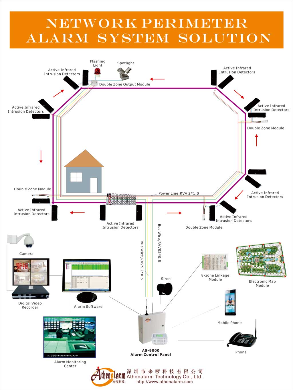
A Perimeter Precaution Alarm System (PPAS) is a hybrid physical security platform that combines a Perimeter Intrusion Detection System (PIDS) with a commercial Intrusion Alarm System (IAS), structured around a multi-drop addressable fieldbus communication backbone. This architectural deployment serves as a comprehensive network perimeter alarm system solution engineered for high-security environments. The system’s primary engineering function is to detect, classify, and transmit intrusion events at the outermost boundary of a protected facility before an adversary penetrates interior asset zones. To achieve this, the underlying burglar alarm infrastructure integrates heavy-duty physical sensors such as a high-reliability door contact to seal perimeter access pathways, paired with localized components like a high-visibility warning light to instantly deter targets at the breach zone.
The PPAS boundary begins at the exterior physical perimeter — fence lines, clear zones, gate structures, or building facades — where physical transducers are mounted and sensor fields are established. The data boundary terminates at the network edge interface or dry-contact output relays of the Alarm Control Panel (ACP), where processed telemetry is handed over to the Security Operations Center (SOC), Video Management System (VMS), or Central Monitoring Station (CMS).
This architecture positions the PPAS as a low-latency initiator within the broader enterprise security stack. As a result, configuring a unified network alarm monitoring system solution broadens the operational scope, adapting fluidly across multiple industrial network alarm monitoring system application profiles. Rather than reacting to building-level intrusion events, the system generates upstream detection signals that trigger coordinated responses across access control, surveillance, and remote monitoring platforms simultaneously.
The operational significance of this early-detection function scales directly with asset exposure. Facilities operating high-value logistics, critical energy infrastructure, or sensitive data infrastructure cannot afford the detection latency of interior-only alarm systems. Perimeter detection creates a response window — typically measured in minutes — that transforms security operations from reactive containment to active threat neutralization at the boundary layer.
The engineering challenge underlying all PPAS deployments is transmitting that detection signal reliably across extended field distances, through harsh environmental conditions, without accumulating voltage degradation, communication failures, or excessive nuisance alarm rates that erode operational trust in the system.
2. Physical Detection Layer: Sensor Modalities and Transducer Selection
The physical detection layer converts mechanical, optical, or electromagnetic energy at the perimeter boundary into digital state changes that feed the fieldbus communication network. Sensor modality selection determines both the probability of detection and the baseline nuisance alarm rate — making it one of the most consequential engineering decisions in the system design phase.
Volumetric Microwave Barriers emit continuous microwave radiation across a defined corridor. When a body mass interrupts or distorts the received signal, the transducer generates an alarm state. Microwave barriers perform reliably in open terrain and maintain detection capability across adverse weather, but require clear line-of-sight corridors and exhibit sensitivity to foliage movement and large fauna.
Active Infrared Beams project one or more infrared beam arrays between transmitter and receiver columns. Physical interruption triggers the alarm. Multi-beam configurations reduce false triggers from small animals or airborne debris, but are subject to optical obstruction from seasonal vegetation growth, heavy fog, or frost accumulation on lens surfaces.
Fence-Mounted Vibration and Microphonic Sensors transduce mechanical energy from fence fabric disturbance — cutting, climbing, or forced displacement — into analog voltage signals. In modern infrastructure deployment, integrating an intelligent digital vibration detector allows the system to analyze digital frequency shifts and isolate true intrusion signatures from environmental noise. These sensors are closely coupled to the structural properties of the fence: tension inconsistency, loose fabric sections, or heavy truck vibration from adjacent roadways all generate signal artifacts that must be filtered during calibration.
Seismic and Fiber Optic Acoustic Sensors detect ground-borne or structure-borne disturbances at high sensitivity levels. Fiber optic acoustic sensing is particularly effective in high-security perimeter configurations at substations or data centers, where it is frequently deployed in combination with bistatic microwave barriers to form dual-technology verification layers that reduce nuisance alarm rates without compromising the probability of detection.
Dual-Technology Sensors require simultaneous or near-simultaneous triggering of two independent detection modalities before generating a confirmed alarm state. This AND-logic architecture significantly reduces environmental false triggers while maintaining acceptable detection sensitivity for human intrusion profiles. Furthermore, secondary confirmation lines inside the boundary perimeter frequently utilize a high-performance PIR motion sensor or a wide-area wide-angle PIR motion sensor to verify localized movement after an initial boundary break.
3. RS-485 Addressable Fieldbus Physical Layer Specification
The baseline communication standard for addressable PPAS field infrastructure is the RS-485 physical layer, operating via differential voltage signaling over shielded twisted pair (STP) cabling. Differential signaling transmits data as a voltage difference between two conductors rather than as an absolute voltage level referenced to ground. This architecture provides high common-mode noise rejection, making RS-485 the preferred physical layer for outdoor industrial environments exposed to electromagnetic interference (EMI) from high-voltage transmission lines, industrial switchgear, and diesel generator exhaust systems.
The multi-drop fieldbus topology connects multiple zone addressable transponders along a single shared physical cable path, eliminating the home-run point-to-point wiring loops that traditional perimeter alarm systems required. Each transponder is assigned a unique logical address within the panel’s polling table. The Alarm Control Panel (ACP) acts as the bus master, sequentially polling each node for state data, fault conditions, and tamper tokens on a cyclic basis.
RS-485 fieldbus architectures support bus segments of approximately 1,200 meters before signal integrity degrades below reliable communication thresholds. For larger perimeter deployments, repeater modules or distributed field power supplies extend the effective communication range while maintaining voltage levels above the minimum operating threshold at the furthest node.
Two critical physical layer requirements govern bus integrity across the full cable length. First, the shield of the STP cable must maintain continuity through all junction boxes and node enclosures, with a single-point earth ground connection to prevent induced ground loops. Parallel routing alongside high-voltage AC conduits must be avoided, as inductive coupling introduces AC noise components into the differential signal path. Second, the bus must be properly terminated at both physical endpoints — a requirement that becomes the source of one of the most common commissioning failures in field deployments, addressed in the fault isolation section below.
4. Mitigating Signal Attenuation and Voltage Drop
Copper wire resistance accumulates linearly with distance. As a fieldbus run approaches its physical length maximum, the combined DC resistance of the cable path imposes a voltage drop governed by Ohm’s Law:
V_drop = I × R
where I represents the cumulative current draw of all field nodes on the segment and R represents the total loop resistance of the cable run. For large perimeter deployments — particularly those spanning 500 meters to several kilometers — this voltage drop calculation must be completed before cable gauge selection is finalized.
The failure mode is not an immediate communication collapse. Voltage drop manifests gradually and conditionally. Under normal daytime operating conditions, node current draw is modest, and bus voltage remains within acceptable ranges. When field conditions change — temperatures drop at night, activating auxiliary heaters inside sensor enclosures, or infrared illuminators powering up for low-light operation — current draw peaks across all active nodes simultaneously. Line voltage drops below the minimum operating threshold (V_min) at the most distant transponders, causing localized brownout cycles. These brownouts produce recurring “module missing” fault entries in the ACP event log, typically misdiagnosed during commissioning as device hardware failures.
Mitigation strategies include selecting heavier conductor gauges — moving from 22 AWG to 18 AWG or 14 AWG depending on run length and current budget — or deploying distributed supervised field power supplies at intermediate points along the bus. Distributed power supplies inject regulated voltage directly into the bus at calculated intervals, compensating for resistive losses without requiring complete cable replacement.
Power budget calculations must account for peak current scenarios, not nominal operating conditions, to ensure stable communication across all environmental states throughout the system’s operational lifetime.
5. Protocol Matrix: SIA DC-09 Cloud Uplink and VMS Integration
Once the Alarm Control Panel (ACP) evaluates the fieldbus state matrix and classifies an alarm event, it must propagate that event upstream to the Central Monitoring Station (CMS) receiver and trigger real-time responses in integrated security subsystems. To streamline this data orchestration at the monitoring tier, deploying a dedicated network alarm center management software ensures real-time visualization and log management of all multi-drop telemetry.
The dominant modern protocol for this upstream transmission path is SIA DC-09 (IP Event Reporting). SIA DC-09 encapsulates structured alarm tokens — formatted as SIA 2000 or Contact ID (SIA DC-05) data strings — into standard UDP or TCP packets for transmission over IP or LTE cellular networks. A critical operational feature of SIA DC-09 is its supervised path mechanism: the panel and CMS receiver exchange continuous encrypted polling heartbeats at configurable intervals. If the communication path is severed, jammed, or degraded, the CMS receiver registers a supervised path failure within seconds and escalates a high-priority loss-of-communication alert through dispatch workflows — a direct countermeasure against communication jam attacks.
Contact ID, the legacy DTMF tone-based standard originally designed for PSTN analog telephone networks, remains operationally present in mixed-generation deployments. In modern configurations, Contact ID strings are digitized and wrapped inside SIA DC-09 IP frames, preserving event code formatting while eliminating dependence on analog carrier infrastructure, which is being sunset by telecommunications providers.
For Video Management System (VMS) integration, the ACP interfaces via programmatic SDK commands or dry-contact relay outputs. ONVIF Profile M-compatible panels issue direct PTZ camera commands upon zone violation — slewing cameras to predefined visual verification presets, initiating edge recording, and populating the VMS event timeline with synchronized alarm metadata. This automation eliminates the manual camera-hunting step that historically delayed visual verification in monitoring center workflows.
MQTT and WebSockets protocols are increasingly deployed in cloud-connected and edge-computing PPAS architectures, supporting lightweight real-time telemetry streaming to dashboards and distributed microservice platforms.
6. Class A Loop Redundancy vs. Linear Topology Failures
The physical topology of the RS-485 fieldbus — whether deployed as a linear segment or a closed loop — determines the system’s resilience profile against cable damage events.
A linear topology routes the fieldbus from the ACP outward through each zone addressable transponder in sequence, terminating at the furthest node. This configuration minimizes cable consumption and simplifies conduit routing. The engineering vulnerability is categorical: a single physical cable cut, ground fault, or wiring junction failure anywhere along the bus disables all downstream nodes from that break point to the terminal end. For a large perimeter deployment, a single trench strike or fence-line cable attack can silently drop multiple detection zones before the fault is identified.
A Class A loop topology (equivalent to NFPA Style 7 wiring) routes the fieldbus outward from the ACP through all zone transponders and returns the cable to a secondary input port on the same panel. Under normal operation, the ACP polls from one direction. When a cable break occurs, the panel detects the open circuit condition and immediately injects polling signals from both ends of the loop, maintaining 100% system telemetry and addressability across all field nodes. The system continues operating normally until physical cable repair is executed.
The trade-off is installation cost: loop topologies require approximately twice the cable length for the return run, additional conduit space, and dual-port panel configurations. For critical infrastructure and high-security facilities, this cost differential is justified by continuity of detection during physical attack scenarios targeting the perimeter cable infrastructure itself.
Isolation modules, installed at zone boundaries within the loop, provide an additional layer of fault containment. If a short-circuit fault develops on one segment, the isolation module electrically removes that segment from the bus, preserving communication across all remaining zones while the fault is isolated and repaired.
7. Termination Resistor Requirements and Impedance Matching
RS-485 differential signaling operates as a transmission line at the signal frequencies generated by high-speed polling cycles. When electrical signals propagate along a transmission line and encounter an impedance discontinuity at the physical endpoint, a portion of the signal energy reflects back toward the source. These reflections superimpose onto the forward-traveling signal, distorting the voltage waveform and corrupting data frames in transit.
To absorb signal energy at the bus endpoints and prevent waveform reflections, a 120-ohm termination resistor must be installed in parallel across the signal conductors at each physical end of the RS-485 bus — and only at the two physical endpoints. The 120-ohm value matches the characteristic impedance of standard shielded twisted pair cabling used in PPAS fieldbus deployments.
The failure consequences of incorrect termination are operationally insidious. A missing termination resistor at one end of a long bus run allows reflections to accumulate, producing voltage glitches that the receiving transceivers intermittently misclassify as valid data. A duplicated termination resistor — installed at an intermediate zone node rather than the endpoint — creates an impedance step that partially absorbs the driving signal itself, reducing signal amplitude below reliable detection thresholds at distant nodes.
Both failure modes produce the same observable symptom: random zone transponders intermittently disappear and reappear in the ACP polling table without any physical hardware fault. This phantom polling behavior is frequently misattributed to failing transponder hardware or panel firmware defects during commissioning, driving up diagnostic labor costs and delaying project handover.
Correct termination verification requires a calibrated oscilloscope to visually confirm waveform integrity at the bus endpoints under operational polling conditions. Visual inspection or continuity testing alone cannot identify termination errors, as the resistors may be present but incorrectly positioned along the bus length.
8. Seven Engineering Benefits of a PPAS
8.1 Benefit 1: Early Intrusion Detection Before Asset Exposure
Perimeter detection establishes an alarm response window measured from boundary crossing to interior asset access. For facilities where asset protection, personnel safety, or operational continuity depends on preventing interior penetration, this detection timeline is the primary engineering objective. Sensors deployed at the outermost boundary — fence lines, gate structures, clear zones — generate alarm states before an adversary traverses the distance to a building entry point, providing security teams 3 to 8 minutes of response time depending on facility dimensions.
8.2 Benefit 2: Integrated Security Ecosystem
The ACP functions as the event initiator for the broader security workflow. Zone violations automatically trigger PTZ camera slewing to predefined visual verification presets via ONVIF Profile M commands, activate access control lockdown sequences through dry-contact relay outputs, and dispatch structured SIA DC-09 alarm tokens to the CMS receiver for operator verification and emergency dispatch. Event correlation across the VMS, Access Control System (ACS), and CMS eliminates the manual coordination step that delays response in non-integrated architectures.
8.3 Benefit 3: Scalable Bus-Based Expansion
Addressable fieldbus architecture allows new detection zones to be added by splicing additional zone addressable transponders onto the existing physical bus at the nearest accessible node, provided the ACP’s total address capacity and power budget remain within specification. This incremental expansion model supports phased capital expenditure planning and allows perimeter coverage to grow with facility expansion without requiring new cable infrastructure pulls.
8.4 Benefit 4: False Alarm Reduction Through Engineering
Dual-technology sensors requiring simultaneous activation of two independent detection modalities significantly reduce environmental false triggers. Sensor calibration during commissioning — validated through physical walk tests under varying atmospheric conditions — establishes detection thresholds that discriminate human intrusion profiles from wildlife, wind-driven fence movement, and vehicular vibration. Proper calibration directly determines the system’s nuisance alarm rate, which governs long-term operational trust.
8.5 Benefit 5: Predictive Maintenance and Remote Diagnostics
Bus-based architectures transmit continuous health telemetry alongside alarm data. From a central management interface, operators monitor bus voltage levels, loop current values, individual transponder signal-to-noise ratios, and battery state indicators across the full perimeter. This diagnostic visibility enables predictive maintenance — identifying degrading components before they generate active faults — reducing emergency dispatch frequency and extending equipment service life.
8.6 Benefit 6: Lower Total Cost of Ownership
Replacing home-run point-to-point wiring with addressable fieldbus topology eliminates the majority of copper cable material on large perimeters. Sourcing these fieldbus-compatible components from an experienced burglar alarm manufacturer guarantees structural hardware alignment and lowers initial capital procurement outlays. A single RS-485 bus connecting 30 to 50 zone transponders replaces 30 to 50 individual cable runs, reducing trenching labor, conduit fill, and cable material costs by substantial margins at scale. Simplified wiring also reduces troubleshooting complexity during fault events, accelerating repair time and lowering operational expenditure over the system lifecycle.
8.7 Benefit 7: Bus-Line Architecture for Large Facilities
Large perimeters spanning industrial parks, data centers, airports, or substations require detection coverage across distances where point-to-point wiring becomes physically and economically impractical. Addressable fieldbus architecture, deployed as a linear segment or Class A loop, provides granular zone addressability across multi-kilometer perimeters on a single shared physical cable path. Advanced ACP platforms support extended communication distances, distributed intelligence at zone nodes, and structured zone naming that renders precise alarm location data on operator consoles rather than generic “perimeter alarm” indications.
9. Engineering Constraints and Real-World Trade-Offs
9.1 Shared-Media Failure Risks
The primary architectural vulnerability of fieldbus systems is shared communication media. Because all zone transponders share a single physical cable path, a short-circuit fault on one bus segment disables telemetry from all downstream nodes simultaneously. Without isolation modules at zone boundaries, a single cable fault can silently remove multiple detection zones from the operational picture — potentially during an active intrusion event. Linear topologies without loop redundancy amplify this risk to its maximum expression.
9.2 Ground Loop Diagnostics
Multi-kilometer shielded cable runs traversing industrial facilities accumulate exposure to stray AC voltages leaking from aging electrical infrastructure, improperly bonded structural metalwork, and external equipment ground paths. When the cable shield connects to earth ground at more than one node, differential ground potential between grounding points drives stray current through the shield conductor. This current couples into the signal pair, injecting low-frequency AC noise components that manifest as intermittent data corruption on the bus. Ground loops are among the most difficult fieldbus faults to diagnose without specialized field instrumentation — specifically a clamp-type AC current meter placed on the shield conductor to confirm stray current flow.
9.3 Detection Sensitivity vs. Nuisance Alarm Rate
Maximizing the probability of detection requires setting sensor thresholds at high sensitivity levels. High sensitivity captures stealthy intrusion profiles — slow-moving adversaries, lightweight individuals, carefully managed fence crossings — but simultaneously captures environmental noise events. Security teams that experience high nuisance alarm rates progressively lower sensitivity thresholds to reduce dispatch volume, creating detection blind spots that sophisticated adversaries can exploit. This operational drift from engineering intent to alarm-fatigue management represents one of the most significant long-term risks in perimeter system operation.
9.4 Power Budget Planning
Peak alarm current scenarios — not nominal operating conditions — govern cable gauge selection and field power supply placement. Designs that calculate voltage budgets against average current draw fail under peak load conditions when multiple illuminators, heaters, and alarm relays activate concurrently across a cold-night event. Under-specified cable gauges produce marginal voltage conditions at distant nodes that progressively worsen as cable insulation ages and connector resistance increases over the system’s operational lifetime.
10. Deployment Lifecycle: Engineering Phases, Risks, and Mitigations
10.1 Threat Assessment and Zone Mapping
Risk-vector analysis identifies probable breach points — gates, utility corridors, fence corners, low-visibility sections — and maps them to sensor technology selections. This phase must produce a formal zone map that assigns sensor modality, detection field geometry, and connectivity path to each perimeter segment before equipment procurement begins.
Risk: Incomplete threat modeling leaves low-visibility breach points unprotected. Mitigation: Validate zone maps against physical site photography and topographic surveys.
10.2 Site Survey
Validate line-of-sight paths for microwave and infrared sensors, map EMI sources, assess fence structural integrity, and identify subsurface soil conditions that could affect ground-mount sensor posts. Seasonal vegetation growth trends must be documented — paths that are clear during a summer survey may be obstructed by winter ice accumulation or spring canopy growth.
Risk: Undetected soil instability causes post-installation sensor misalignment. Mitigation: Document GPS coordinates of all sensor mounting positions for comparison during first-year inspections.
10.3 Bus Design and Cable Selection
Complete electrical calculations for cumulative bus voltage drop under peak current scenarios before specifying cable gauge. Map repeater positions and field power supply injection points on the bus diagram. Document termination resistor positions and all junction box locations.
Risk: Under-specified cable gauges create marginal voltage conditions at distant nodes. Mitigation: Apply a minimum 15% voltage margin above V_min at the furthest node under peak load conditions.
10.4 Installation
Execute structural trenching, pull outdoor-rated shielded twisted pair fieldbus cables, install zone addressable transponders in IP66/IP67 weatherproof enclosures, and implement single-point earth grounding schemes at designated nodes. Maintain shielding continuity through all junction boxes.
Risk: Parallel AC conduit routing induces EMI noise into the signal path. Mitigation: Maintain minimum separation distances from high-voltage infrastructure as specified by fieldbus installation standards.
10.5 Commissioning and Sensor Calibration
Calibrate environmental filtering algorithms for each sensor zone through physical walk tests under varying atmospheric conditions. Map logical addresses to physical coordinates in the ACP configuration database. Program inter-system automation logic linking zone alarm states to PTZ camera presets and ACS lockdown sequences.
Risk: Aggressive calibration targeting low nuisance alarm rates reduces probability of detection. Mitigation: Use dual-technology sensor configurations where detection confidence must be maintained without increasing NAR.
10.6 CMS Onboarding
Establish SIA DC-09 transmission profiles with primary and secondary receiver IP addresses. Configure supervised heartbeat intervals and validate that zone-specific alarm identifiers render correctly on CMS dispatcher screens — not as generic perimeter codes.
Risk: Firmware version mismatches between ACP and CMS receiver cards prevent structured event data from rendering correctly. Mitigation: Validate firmware compatibility between ACP and CMS receiver platforms before installation begins.
10.7 Lifecycle Maintenance
Schedule quarterly battery load tests, biannual sensor calibration field reviews, and annual firmware validation cycles. Download diagnostic event logs from the ACP to identify recurring fault patterns that indicate degrading components before active failures occur.
Risk: Deferred battery replacement causes total perimeter security failure during power grid events. Mitigation: Implement battery replacement schedules based on thermal cycling history, not calendar age alone.
11. Operations and Maintenance Model
11.1 Battery Lifecycle Management
Sealed Lead-Acid (SLA) and Lithium Iron Phosphate (LiFePO₄) backup batteries deployed in outdoor field enclosures operate under wide ambient temperature swings — from sub-zero winter conditions to high-temperature summer exposure in unshaded enclosures. This thermal cycling compresses the effective service life of SLA batteries to a 3-to-5 year window under field conditions, significantly shorter than manufacturer ratings established under controlled laboratory temperature environments. Failure to execute systematic load-tested replacement schedules — not voltage-only float tests — risks total perimeter system blackout during local power grid disruptions precisely when security conditions are most demanding.
11.2 Remote Diagnostics and Fleet Monitoring
Modern ACP platforms transmit bus voltage metrics, loop current values, and sensor signal-to-noise ratios over IP network paths to centralized fleet management dashboards. By leveraging a centralized enterprise alarm monitoring system, operators managing multiple sites can monitor the health state of every zone transponder across all facilities from a single interface. Degrading voltage margins, increasing noise floor readings, or recurring module communication retries all appear as leading indicators of impending field faults — allowing technicians to execute targeted maintenance during scheduled visits rather than emergency dispatches.
11.3 Troubleshooting Bus Faults
Software-based remote diagnostics can identify a failing module address instantly. Locating the physical cause of that fault — whether a short circuit, high-resistance connector, moisture ingress at a junction box, or degraded cable insulation along a buried run — requires field instrumentation that most security maintenance teams do not routinely carry. Time-Domain Reflectometer (TDR) meters inject a calibrated signal pulse into the cable and measure the time delay of reflected signal returns, calculating the physical distance to the impedance discontinuity causing the fault. Ground fault location along multi-kilometer buried cable paths without TDR instrumentation requires systematic physical excavation — a process that consumes substantial labor time and disrupts perimeter coverage during the investigation period.
11.4 Firmware Management
Staged firmware validation must precede any panel firmware update on operational systems. Firmware updates that alter polling protocol parameters, address range handling, or integration API behavior can silently break SIA DC-09 heartbeat timing, causing CMS receiver platforms to register supervised path failures and generating high-priority alerts across monitoring networks during the update window. Testing firmware releases on offline or spare panel configurations before production deployment prevents unplanned operational disruptions.
11.5 SLA Considerations
Critical infrastructure PPAS installations carry Tier 1 security system designations. Standard operational SLA parameters require high-severity fault response within 2 to 4 hours of detection, system availability at or above 99.95% uptime, and a maximum nuisance alarm rate below one false alarm per zone per month. These parameters require active monitoring, not passive event logging, and demand rapid escalation pathways from remote diagnostic platforms to field service teams.
12. Deployment Scenarios: Architecture Guidance by Facility Type
12.1 Critical Infrastructure: Substations, Data Centers, and Water Treatment Facilities
Risk profiles at critical infrastructure facilities require zero tolerance for undetected breaches. Similarly, financial assets demand specialized protection, making a network bank alarm monitoring system solution essential, often utilizing an optimized bank ATM alarm monitoring system solution for remote endpoints and a robust network bank vault alarm monitoring system solution to safeguard central deposit zones. Architectural configurations deploy looped Class A fieldbus topologies with hardware isolation modules at every zone boundary interface. Dual-technology sensors — combining seismic fiber optic acoustic sensing with overlapping bistatic microwave barriers — establish confirmed alarm states that minimize nuisance alarm rates without relaxing detection sensitivity. Every copper cable entry point carries lightning surge protection networks. PTZ camera cross-triggering activates automatically on zone violations via ONVIF Profile M commands. Network transmission uses TLS/AES-256 encryption over SIA DC-09 profiles, with mandatory weekly remote path supervision tests to validate communication path integrity.
12.2 Commercial Logistics Hubs and Industrial Parks
Large logistics facilities generate high volumes of legitimate perimeter activity — heavy distribution trucks at loading docks, high-wind events across large open yards, seasonal vegetation around fence lines. The primary deployment challenge is tuning fence-mounted microphonic or accelerometer-based vibration sensors to reject structural vibration from truck impact events while maintaining sensitivity to human climbing attempts. Access Control System integration suppresses alarm states during scheduled logistics vehicle gate cycles, preventing alarm fatigue from routine perimeter access operations. Linear bus topologies are frequently deployed at this scale, with zone isolation modules protecting against the localized cable faults that are more common in high-traffic industrial environments.
12.3 Campuses: Education and Corporate
Campus perimeters prioritize controlled access management over high-threat intrusion interdiction. This architectural logic scales effectively down to commercial and urban properties, matching the design patterns of a network community alarm system solution, a network house alarm system solution, a tailored network hotel alarm system solution, or a localized network store alarm system solution. Sensor calibration targets false alarm minimization to avoid disrupting legitimate pedestrian and vehicular activity. Integration with access control platforms enables time-based alarm arm/disarm scheduling aligned with operational hours. Discrete sensor placement preserves campus aesthetic requirements while maintaining boundary monitoring coverage across extended linear perimeters.
12.4 Retrofit Projects: Legacy Infrastructure Integration
Retrofit deployments present elevated diagnostic complexity. Historical wiring documentation is frequently incomplete or inaccurate, legacy sensors may use proprietary analog interfaces incompatible with modern addressable transponders, and buried conduit conditions are unknown until excavation begins. Addressable bus transponders bridge legacy point-to-point sensor outputs onto modern IP-accessible fieldbus backbones, preserving existing sensor investments. Specialized bus repeaters overcome poor signal quality on deteriorated existing cable plant. Firmware stabilization across mixed hardware generations requires systematic compatibility testing at each integration boundary rather than assumed compatibility based on protocol naming alone.
13. Engineering Decision Matrix: Architecture Selection Framework
13.1 Bus-Line Architecture vs. Point-to-Point Home-Run Wiring
| Engineering Vector | Bus-Line Topology | Point-to-Point Wired |
|---|---|---|
| Front-End Cable Cost | Low / Scalable | Extremely High |
| Fault Isolation | Complex (Shared Media) | Simple (Isolated Path) |
| Expansion Adaptability | High (Drop-in Splicing) | Low (Requires New Pulls) |
| Diagnostic Method | Software Address Tracking | Physical Continuity Testing |
Bus-line architecture is the appropriate selection for medium-to-large perimeters where cable cost, installation timeline, and future expansion flexibility are primary constraints, provided isolation modules are incorporated to manage shared-media fault propagation risk. Point-to-point wiring retains engineering validity only for very small perimeters with a limited number of zones where wiring simplicity and complete zone electrical isolation are operationally prioritized over cost.
13.2 Loop vs. Linear Topology
Class A loop topologies are the correct selection for critical infrastructure, high-security campuses, and any facility where perimeter cable infrastructure is exposed to physical attack vectors — either environmental or adversarial. Linear topologies are acceptable at commercial logistics and lower-security industrial sites where cost constraints are significant and the impact of a temporary zone dropout during a fault event is operationally tolerable. Any site where a single cable cut could silence a tactically significant detection zone should not be deployed with a linear topology.
13.3 Sensor Selection Decision Factors
| Site Condition | Recommended Sensor Modality |
|---|---|
| Clear open corridor | Volumetric Microwave Barrier |
| Linear fence line, moderate traffic | Fence-Mounted Vibration / Microphonic Cable |
| High-security boundary, zero false alarm tolerance | Dual-Technology (Microwave + Fiber Optic Acoustic) |
| Enclosed compound with controlled sight lines | Active Infrared Multi-Beam Barriers |
| Retrofit or mixed terrain | Seismic Sensor + Addressable Transponder Bridge |
13.4 When PPAS Is the Right Architectural Choice
PPAS deployments are justified when the protected facility requires boundary-layer detection before interior penetration, the perimeter spans a distance that makes point-to-point wiring economically impractical, the security operations model requires integrated response automation across surveillance and access control systems, and the operational environment demands remote diagnostic capability across distributed field assets. Facilities that only require building-level alarm coverage and operate within constrained perimeters may be adequately served by conventional intrusion alarm systems without the fieldbus-based perimeter layer.
FAQ
Q1: What is a Perimeter Precaution Alarm System and how does it function?
A Perimeter Precaution Alarm System (PPAS) is a hybrid PIDS/IAS platform that detects, classifies, and transmits intrusion events at the outermost facility boundary before interior asset zones are reached. Physical transducers convert boundary disturbance energy into digital alarm states, which travel via an RS-485 addressable fieldbus to an Alarm Control Panel. The ACP evaluates states and propagates structured events to the CMS and integrated security subsystems via SIA DC-09 over IP or LTE.
Q2: Why is RS-485 the standard physical layer for PPAS fieldbus architectures?
RS-485 uses differential voltage signaling over shielded twisted pair, providing high common-mode noise rejection essential in outdoor industrial environments exposed to EMI from high-voltage infrastructure. It supports multi-drop topologies connecting 30 to 50+ addressable nodes on a single cable, with a reliable communication range of approximately 1,200 meters per segment before repeaters are required. These characteristics make it the preferred physical layer for cost-effective, scalable perimeter alarm bus infrastructure.
Q3: How does a Class A looped fieldbus maintain system operation during a cable cut?
A Class A (Style 7 equivalent) loop routes the fieldbus from the ACP through all zone transponders and returns the cable to a secondary input port on the same panel. If a cable cut occurs, the ACP detects the open circuit and immediately begins polling from both ends of the loop simultaneously, maintaining 100% telemetry and addressability across all field nodes until the physical cable is repaired. This redundancy eliminates the zone dropout vulnerability inherent in linear topologies.
Q4: What causes “module missing” faults on extended RS-485 bus runs?
Intermittent “module missing” errors are primarily caused by cumulative voltage drop (V_drop = I × R) at distant transponders, compounded by peak current loading when field devices activate auxiliary heaters or infrared illuminators simultaneously under low-temperature or nighttime conditions. Line voltage falls below V_min at the furthest nodes, causing transponders to brownout and drop off the polling cycle. Increasing cable conductor gauge or deploying a distributed supervised field power supply at the midpoint resolves this condition.
Q5: What is SIA DC-09 and why is it critical for PPAS upstream communications?
SIA DC-09 is an IP event reporting protocol that encapsulates structured alarm tokens — Contact ID or SIA 2000 data strings — into UDP or TCP packets for transmission over IP or LTE networks. Its supervised path mechanism exchanges continuous encrypted heartbeats between the ACP and CMS receiver. If the communication path is severed or jammed, the CMS detects a supervised path failure within seconds and triggers a high-priority loss-of-communication alert — directly countering communication jam attacks against the monitoring path.
Q6: How does incorrect termination resistor placement affect RS-485 bus performance?
A missing termination resistor at a bus endpoint allows signal reflections to corrupt data frames, causing random transponders to intermittently vanish from the ACP polling table. A duplicated resistor at an intermediate node creates an impedance step that attenuates the driving signal, reducing amplitude below reliable detection thresholds at distant nodes. Both failures produce phantom polling behavior indistinguishable from hardware faults without oscilloscope verification of waveform integrity at the bus endpoints.
Q7: How does PPAS integrate with CCTV and access control systems?
The ACP interfaces with Video Management Systems via ONVIF Profile M SDK commands or dry-contact relay outputs, automatically slewing PTZ cameras to predefined visual verification presets upon zone violation and initiating synchronized edge recording. Access Control System integration cross-references authorized gate opening sequences with perimeter alarm states, suppressing false alarms during scheduled logistics operations and enabling coordinated lockdown sequences when boundary violations occur outside authorized access windows.
Q8: How long do backup batteries last in outdoor PPAS field enclosures?
Sealed Lead-Acid and LiFePO₄ batteries deployed in outdoor field enclosures under wide ambient temperature cycling typically achieve 3 to 5 years of effective service life — significantly below laboratory-rated lifetimes. Quarterly load testing — applying a calibrated discharge load and measuring voltage drop under current draw — is required to identify capacity degradation before the battery fails to sustain the system during a power grid event. Float voltage checks alone do not detect capacity loss in aged SLA batteries.
Q9: When should isolation modules be installed on a PPAS fieldbus?
Isolation modules should be installed at zone boundaries in any bus deployment where a short-circuit fault on one segment must not disable telemetry across adjacent zones. They are mandatory in Class A loop topologies to allow the panel to isolate a faulted segment while maintaining communication through the remainder of the loop. They are strongly recommended at every zone interface in critical infrastructure deployments where simultaneous loss of multiple detection zones represents an unacceptable security exposure.
Q10: What distinguishes PPAS deployment at a critical infrastructure site versus a logistics hub?
Critical infrastructure sites deploy Class A looped bus topologies, dual-technology sensors, hardware isolation modules at every zone boundary, lightning surge protection on all copper entries, and TLS-encrypted SIA DC-09 transmission with mandatory weekly path supervision testing. Logistics hub deployments typically use linear bus topologies with fence-mounted vibration sensors calibrated to reject heavy truck structural vibration, with ACS integration managing alarm suppression during scheduled vehicle gate cycles to prevent alarm fatigue from routine logistics operations.
